
Bridging the Gap: From Maker to Industrial Automation
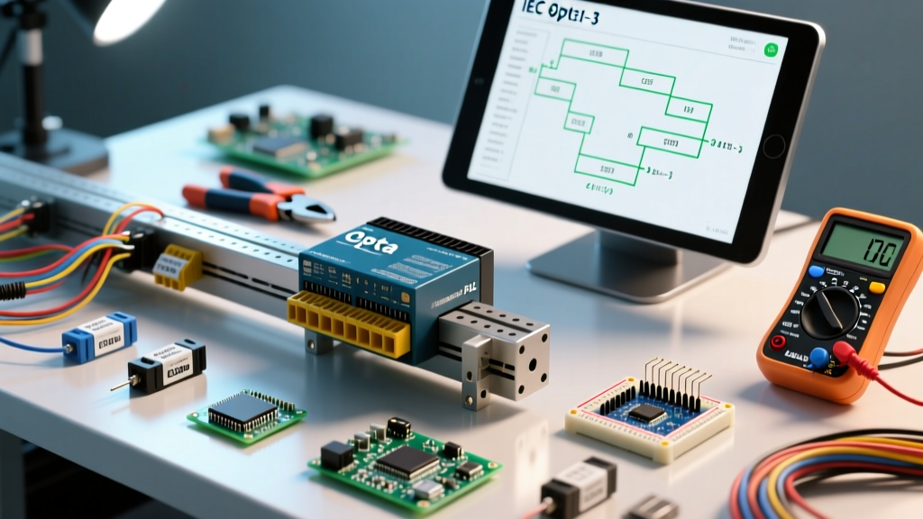
The transition from breadboard prototyping to reliable industrial automation requires hardware that can survive harsh electrical environments while maintaining the flexibility of modern microcontrollers. The Arduino Opta was engineered precisely for this intersection. Developed in partnership with Finder S.p.A., the Opta is a micro PLC (Programmable Logic Controller) and IoT gateway built around the powerful STMicroelectronics STM32H747XI dual-core processor (Cortex-M7 at 480MHz and Cortex-M4 at 240MHz).
Unlike standard development boards, the Opta features optically isolated inputs, electromechanical relay outputs, and native support for IEC 61131-3 programming languages. In this comprehensive 2026 guide, we will walk through the exact wiring protocols, IDE configurations, and Ladder Logic programming steps required to deploy the Arduino Opta in a real-world industrial control panel.
Hardware Matrix: Selecting Your Opta Variant
Before wiring your control panel, you must select the correct SKU for your network topology. As of 2026, the Opta lineup consists of three primary models, all sharing the same 2MB Flash, 1MB RAM, and 8-input/4-output I/O architecture.
| Model | Connectivity | Protocol Support | Est. Price (2026) |
|---|---|---|---|
| Opta Lite | Ethernet (10/100) | Modbus TCP, HTTP, MQTT | $185 USD |
| Opta RS485 | Ethernet + RS485 | Modbus TCP, Modbus RTU | $225 USD |
| Opta WiFi | Ethernet + Wi-Fi/BLE | Modbus TCP, MQTT, TLS | $255 USD |
Note: The RS485 variant is essential if you are integrating legacy variable frequency drives (VFDs) or older Modbus RTU sensor networks into your modern IoT architecture.
Phase 1: DIN-Rail Mounting and Electrical Wiring
The Opta is designed for standard 35mm DIN rail mounting. Proper wiring is critical; industrial environments are plagued by electromagnetic interference (EMI) and voltage transients that can destroy improperly configured I/O.
Power Supply and Input Configuration
The Opta requires a 12-24VDC power supply connected to the dedicated power terminals. Do not attempt to power the unit via the USB-C port in a production environment; USB-C is strictly for debugging and firmware flashing.
The 8 inputs (I0 to I7) are highly versatile but require specific attention:
- Digital Mode (24VDC): The inputs feature built-in optocouplers. They can read standard 24VDC PNP sensor outputs. The threshold for a logical HIGH is typically >15VDC.
- Analog Mode (0-10V): Inputs I0 through I3 double as 12-bit analog inputs. To use them for 0-10V proportional sensors (like pressure transducers or temperature transmitters), you must configure the hardware dip switches located under the front faceplate, or configure them via the Arduino PLC IDE hardware mapping tool.
Output Relay Protection and Snubber Circuits
The Opta features 4 electromechanical relay outputs (O0 to O3), rated for 10A at 250VAC. However, this rating applies strictly to resistive loads.
CRITICAL WARNING: If you are switching inductive loads (solenoids, contactor coils, or small motors) on 24VDC, the effective current rating drops drastically due to arc generation. Switching >2A inductive DC loads without a flyback diode or RC snubber will cause the internal relay contacts to weld shut, permanently destroying the output channel.
Actionable Fix: For any inductive load, wire an RC snubber (e.g., 100Ω resistor in series with a 0.1µF capacitor) directly across the load terminals, or use the Opta's 10A relays to trigger the coil of a larger, external industrial contactor.
Phase 2: Environment Setup and IEC 61131-3
While you can program the Opta using the standard, free Arduino IDE 2.x using C/C++, doing so ignores the device's primary purpose as a PLC. To utilize standard industrial automation languages, you must use the Arduino PLC IDE.
The PLC IDE supports all five IEC 61131-3 languages:
- Ladder Diagram (LD): Visual, relay-logic style programming (best for discrete I/O).
- Function Block Diagram (FBD): Graphical data-flow programming.
- Structured Text (ST): High-level Pascal-like syntax (best for complex math and data arrays).
- Instruction List (IL): Low-level assembly-like language.
- Sequential Function Chart (SFC): State-machine based flow control.
Licensing Note: The Arduino PLC IDE requires a paid subscription (Standard or Professional tier) for commercial deployment, though a free trial is available for initial hardware validation.
Phase 3: Programming a Seal-In Circuit in Ladder Logic
Let's program a classic industrial 'Start/Stop' seal-in (latching) circuit. We will map a physical Normally Open (NO) Start button to Input I0, a Normally Closed (NC) Stop button to Input I1, and a motor contactor to Output O0.
- Hardware Mapping: Open the PLC IDE and navigate to the Hardware Configuration tab. Map physical input
I0to a boolean variable namedSTART_BTN, andI1toSTOP_BTN. Map physical outputO0toMOTOR_COIL. - Create the LD Network: Insert a new Ladder Diagram task. Drag a 'Normally Open' (NO) contact onto the rung and assign it to
START_BTN. - Add the Stop Condition: Drag a 'Normally Closed' (NC) contact in series with the start button. Assign it to
STOP_BTN. Important: Because physical stop buttons are usually wired NC for safety (so a broken wire stops the machine), the PLC logic must treat the received 24V signal as a permissive state. - Create the Seal-In Branch: Add a parallel branch around the
START_BTN. Place an NO contact on this branch and assign it toMOTOR_COIL. This ensures that once the output is energized, it bypasses the start button to maintain the circuit. - Assign the Output Coil: At the end of the rung, place an output coil and assign it to
MOTOR_COIL. - Compile and Flash: Connect the Opta via USB-C, compile the project, and transfer it to the STM32H747XI. The Opta will retain this program in its non-volatile memory and execute it immediately upon 24VDC power-up, even without a network connection.
Advanced Troubleshooting and Edge Cases
Even with perfect code, physical layer issues can cause erratic Opta behavior. Here are specific failure modes to watch for during commissioning:
- Analog Input Ground Loops: If your 0-10V analog sensors read erratically or show a 1-2V offset, you likely have a ground loop. The Opta's analog inputs are referenced to the PLC's internal ground. Ensure the 0V reference of your external sensor power supply is bonded to the Opta's 0V terminal to establish a common equipotential ground.
- Watchdog Timer Resets: The STM32H747XI features a hardware watchdog. If your Structured Text contains an infinite loop or a blocking delay function that exceeds the watchdog timeout (default is often 2-4 seconds in PLC configurations), the Opta will hard-reset. Always use non-blocking timer blocks (TON/TOF) in IEC 61131-3 instead of standard C++
delay()functions. - RS485 Termination Errors: When using the Opta RS485 for Modbus RTU over long cable runs (>50 meters), signal reflection will cause CRC checksum errors. Ensure the 120Ω termination resistor is physically enabled on the Opta (via internal jumper or dip switch, depending on the board revision) and that the cable shield is grounded at one end only to prevent low-frequency ground currents.
Conclusion
The Arduino Opta successfully bridges the gap between the accessibility of the Arduino ecosystem and the rigorous demands of industrial automation. By respecting the electrical limits of the I/O stage, utilizing proper snubber circuits, and leveraging the IEC 61131-3 standard via the PLC IDE, engineers can deploy robust, cloud-connected control systems that rival traditional PLCs costing three times as much.