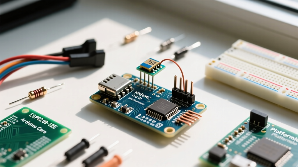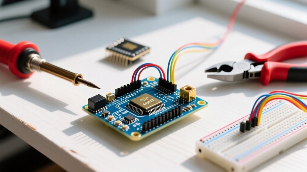

The Great Debate: PWM Illusion vs. True Arduino Analog Out
If you have spent any time on maker forums, you have inevitably encountered the rite of passage: a beginner asking why their LED flickers or their audio sounds like a robotic buzz when using analogWrite(). The harsh reality of the classic ATmega328P (Arduino Uno/Nano) is that it does not possess a true Digital-to-Analog Converter (DAC). Instead, it relies on Pulse Width Modulation (PWM). While PWM is excellent for motor control and LED dimming, it outputs a square wave, not a continuous DC voltage.
As we navigate the hardware landscape in 2026, the maker community has developed a wealth of workarounds, libraries, and hardware add-ons to achieve genuine arduino analog out capabilities. This roundup curates the most reliable community-tested solutions, from software-defined filtering to dedicated I2C DAC modules, ensuring your next project outputs clean, precise waveforms.
Silicon Showdown: AVR vs. Modern ARM & ESP Architectures
Before buying external hardware, it is crucial to understand what your microcontroller's silicon actually supports. The community frequently highlights a massive pitfall regarding modern Espressif chips, specifically the transition from the original ESP32 to the newer ESP32-S3 and ESP32-C3 variants.
| Microcontroller | Native Analog Out Type | Resolution | Community Verdict |
|---|---|---|---|
| ATmega328P (Uno/Nano) | PWM only (Pins 3,5,6,9,10,11) | 8-bit (490Hz/980Hz) | Requires RC filter or external DAC for true DC. |
| ESP32 (Original) | True DAC (GPIO25, GPIO26) | 8-bit | Great for basic audio, but limited to 0-3.3V range. |
| ESP32-S3 / C3 | PWM / I2S only | N/A (No native DAC) | Warning: Broke legacy code. Use I2S DAC or external I2C DAC. |
| SAMD21 (Zero / Nano 33 IoT) | True DAC (Pin A0) | 10-bit | Excellent native 0-3.3V true analog output. |
| Teensy 4.1 | PWM + I2S Audio | High-Res I2S | Overkill for simple DC, but unmatched for audio synthesis. |
Community Consensus: "Never assume a new dev board has a DAC just because its predecessor did. Always check the silicon datasheet for the 'DAC' peripheral block before designing your PCB footprint." — EEVblog Forum Hardware Design Thread, 2025.
Top External DAC Modules Recommended by Makers
When native silicon fails you, the community universally points to a few breakout boards that solve the arduino analog out problem with minimal wiring.
1. The Gold Standard: Microchip MCP4725 (12-Bit I2C DAC)
Priced around $4.95 to $6.50 depending on the breakout vendor (Adafruit, SparkFun, or generic clones), the MCP4725 is the most documented external DAC in the Arduino ecosystem. It communicates via I2C and provides a single 12-bit (0-4095) analog output.
- Default I2C Address:
0x62 - Voltage Range: 2.7V to 5.5V (Output scales to VDD)
- Settling Time: 6µs (Fast enough for low-fidelity audio and precise DC motor control loops)
- Pro-Tip: The MCP4725 features an onboard EEPROM. You can program a default power-on voltage, eliminating the 'floating pin' glitch that occurs during the Arduino bootloader sequence.
For implementation, the community heavily favors the official Microchip MCP4725 datasheet for register mapping, alongside the Adafruit wrapper library for quick prototyping.
2. The Audio Specialist: MAX98357A (I2S to Analog)
If your goal for analog out is audio playback, PWM filtering will result in terrible Signal-to-Noise Ratios (SNR). The community standard for I2S audio on ESP32 and SAMD boards is the MAX98357A. It takes digital I2S data and outputs amplified, filtered analog audio directly to a speaker. Expect to pay roughly $3.00 for a generic breakout.
3. The Old-School Hack: R-2R Resistor Ladder
For those who refuse to use I2C and need parallel data output, building an 8-bit R-2R ladder using standard resistors is a classic university lab exercise. You will need nine 10kΩ and eight 20kΩ resistors. Critical Edge Case: You must use 1% or 0.1% tolerance metal film resistors. Standard 5% carbon film resistors will introduce severe non-linearity (missing codes) in your analog output, a failure mode that frustrates many beginners.
Forum Wisdom: Filtering PWM into True DC
If you are stuck with an ATmega328P and cannot wait for a DAC module to ship, you must convert the 490Hz/980Hz PWM square wave into a smooth DC voltage using an RC Low-Pass Filter. The community has refined the component values through years of trial and error.
Calculating the Cutoff Frequency
The formula for the RC filter cutoff frequency is fc = 1 / (2 * π * R * C). Your goal is to set fc at least one decade (10x) lower than the PWM frequency to adequately smooth the ripple.
Community-Tested Component Pairings
- For Slow DC Control (e.g., Power Supply Reference, Motor Bias): Use a 10kΩ resistor and a 10µF electrolytic capacitor. This yields a cutoff of ~1.6Hz. The ripple is virtually non-existent, but the step-response time is slow (~15ms to settle). Do not use this for audio.
- For Audio / Fast Waveforms (e.g., Sine Wave Generation): You must first increase the Uno's PWM frequency to ~31kHz by modifying Timer1 registers. Then, use a 1kΩ resistor and a 10nF ceramic capacitor. This yields a cutoff of ~15.9kHz, preserving audio frequencies while filtering the 31kHz switching noise. Ceramic is mandatory here; electrolytics have too much Equivalent Series Resistance (ESR) at high frequencies.
Curated Learning Resources & Code Repositories
To master arduino analog out, bookmark these community-vetted resources. They bypass the superficial tutorials and dive into the register-level mechanics required for professional-grade results.
- Official Arduino PWM Reference: The foundational Arduino analogWrite() documentation remains the best starting point for understanding timer limitations and pin mappings across different architectures.
- Espressif ESP-IDF DAC Peripherals: If you are using the original ESP32, the ESP-IDF DAC API reference is essential. It details how to bypass the Arduino core's limitations and use the DAC's built-in cosine waveform generator for testing analog circuits without writing complex math loops.
- Teensy Audio Library: For advanced users, Paul Stoffregen’s Teensy Audio Library provides a visual GUI design tool. It allows you to route virtual patch cables between oscillators, filters, and I2S DAC outputs, completely abstracting the DMA and interrupt handling required for high-fidelity analog synthesis.
Troubleshooting Noisy Analog Outputs
Even with a perfect 12-bit DAC, makers frequently report 'noisy' or 'drifting' analog readings when feeding the signal into op-amps or ADCs. The community identifies three primary culprits:
1. Ground Loops and USB Noise
Powering your Arduino via a laptop USB port injects high-frequency switching noise from the PC's power supply directly into the microcontroller's ground plane. Fix: Isolate the analog ground using a dedicated linear voltage regulator (like an LM7805 or an LDO like the AMS1117-3.3) powered by a battery or isolated wall-wart when precision below 10mV is required.
2. I2C Bus Capacitance
When wiring an MCP4725 DAC over long distances (>30cm), the parasitic capacitance of the wires degrades the I2C square waves, causing communication dropouts and frozen analog voltages. Fix: Lower the I2C clock speed to 100kHz and use 2.2kΩ pull-up resistors instead of the standard 4.7kΩ to sharpen the rise times.
3. Output Impedance Mismatch
The MCP4725 has an output impedance that varies with the DAC code, sometimes reaching several kilo-ohms. If you connect this directly to a low-impedance load (like a 50Ω coaxial cable or a heavy motor driver), the voltage will sag drastically. Fix: Always buffer your DAC output using a rail-to-rail operational amplifier (such as the MCP6002 or TLV2462) configured as a unity-gain voltage follower.
Final Thoughts
Achieving a clean, reliable arduino analog out requires moving past the basic analogWrite() function and understanding the physical realities of your hardware. Whether you are slapping an RC filter on an Uno's PWM pin, leveraging the native 10-bit DAC on a SAMD21, or wiring up an I2C MCP4725 for lab-grade precision, the maker community has already mapped the pitfalls. Use the resources and hardware hacks outlined above to ensure your voltage signals are as smooth and accurate as your code intends them to be.