
Introduction to the Arduino Opta PLC
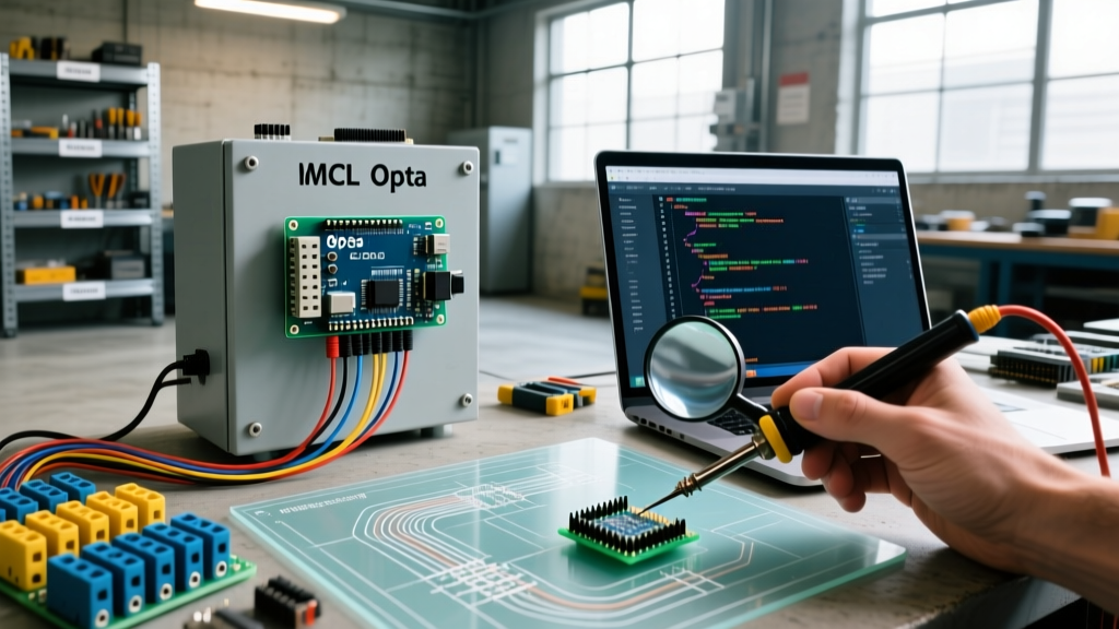
The convergence of Operational Technology (OT) and Information Technology (IT) has created a massive demand for edge devices that can speak both traditional industrial protocols and modern cloud APIs. Enter the Arduino Opta PLC, a secure, easy-to-use micro Programmable Logic Controller developed in partnership with Finder. Unlike standard Arduino boards designed for prototyping, the Opta is engineered for DIN-rail mounting, 24V DC industrial environments, and strict electromagnetic compatibility (EMC) standards.
At its core, the Opta utilizes the STM32H747XI dual-core processor (Arm Cortex-M7 at 480MHz and Cortex-M4 at 240MHz), providing ample overhead for complex IEC 61131-3 logic and simultaneous TLS-encrypted MQTT cloud communication. In this 2026 tutorial, we will walk through the exact hardware wiring, PLC IDE configuration, and Arduino Cloud integration required to deploy the Opta in a real-world manufacturing or facility management scenario.
Hardware SKUs and 2026 Pricing Matrix
Before writing a single line of Ladder Logic, you must select the correct SKU for your environment. The Opta lineup is segmented by connectivity needs. Below is the current matrix for the three primary models available:
| Model / SKU | Connectivity | Approx. Price (2026) | Best Use Case |
|---|---|---|---|
| Opta Lite (AFG00001) | Ethernet, USB-C | $185.00 | Hardwired control panels, local HMI integration |
| Opta RS485 (AFG00002) | Ethernet, USB-C, RS485 | $215.00 | Modbus RTU networks, legacy sensor polling |
| Opta WiFi (AFG00003) | Ethernet, USB-C, Wi-Fi, BLE | $240.00 | Retrofit projects, distributed edge IoT nodes |
Note: All models share the same I/O configuration: 8 opto-isolated analog/digital inputs and 4 SPST electromechanical relay outputs (10A @ 250VAC).
Step 1: Industrial Wiring and Safety Protocols
CRITICAL SAFETY WARNING: The Arduino Opta is an IP20 rated device. It must be installed inside a grounded, NEMA-rated (or IP65+) electrical enclosure. The relay outputs switch mains voltage. Always use proper ferrules on your 16-22 AWG wires and ensure the main breaker is locked out (LOTO) before terminating the 10A relay outputs.
Powering the Opta
The Opta requires a nominal 24V DC power supply (acceptable range: 11V to 30V DC). Do not attempt to power this device via USB-C in a production environment; USB-C is strictly for programming and local serial debugging. Connect your 24V DC positive to the +V terminal and the DC common to the 0V terminal. Ensure your power supply can source at least 1.5A to account for the inrush current of the internal relays and the ATECC608B secure element boot sequence.
Configuring the 8 Universal Inputs
The 8 inputs (I1 to I8) are software-configurable. By default, they read 0-10V analog signals. If you are wiring a standard industrial 4-20mA pressure transducer, you do not need external shunt resistors. The Opta features internal precision shunts that are activated via the Arduino PLC IDE hardware configuration menu. Simply wire the transducer's signal wire to the input terminal and the common to the 0V reference.
Step 2: Configuring the Arduino PLC IDE
Unlike the standard Arduino IDE which uses C++, the Opta is programmed using the Arduino PLC IDE. This environment supports all five IEC 61131-3 languages: Ladder Diagram (LD), Function Block Diagram (FBD), Sequential Function Chart (SFC), Structured Text (ST), and Instruction List (IL).
Licensing: The PLC IDE requires a valid license. As of 2026, a Maker license costs roughly $24.99/year, while Enterprise deployments utilize floating licenses tied to Arduino Cloud organizational accounts.
Understanding Memory Mapping
When programming in LD or ST, you do not use standard Arduino pin numbers (e.g., pinMode(2, INPUT)). Instead, you use standard PLC memory addresses:
- %IX0.0 to %IX0.7: Digital/Analog Inputs (I1 to I8)
- %QX0.0 to %QX0.3: Relay Outputs (O1 to O4)
- %IX1.0: Built-in Ethernet Link Status
- %QX1.0 to %QX1.3: Front-panel Status LEDs
Step 3: Programming a Time-Proportioning Control Loop
Let's build a practical application: a time-proportioning temperature controller for an industrial oven. Because the Opta has relay outputs (not analog 0-10V outputs), we will use a PWM-style duty cycle on Relay 1 (%QX0.0) to control a solid-state relay (SSR) that switches the heating elements.
- Define Variables: Create global variables for
SetPoint(REAL),ProcessValue(REAL), andHeaterOutput(TIME). - Read the Sensor: Map %IW0 (Input 1) to the
ProcessValue. Apply a moving average filter block to eliminate EMI noise from the heating elements. - PID Block: Insert the standard
PIDfunction block. Set the Kp, Ki, and Kd parameters. Route the output to a 0-100% integer. - Duty Cycle Conversion: Use a comparator and an on-delay timer (TON) to convert the 0-100% PID output into a 10-second time base. If the PID output is 60%, the relay %QX0.0 will remain HIGH for 6 seconds and LOW for 4 seconds.
Pro-Tip: Never use the internal electromechanical relays for rapid PWM switching (e.g., 1Hz or faster). Mechanical relays will suffer contact welding and fail within weeks. Always use the Opta's internal relay to trigger an external, zero-crossing SSR for high-frequency thermal control.
Step 4: Bridging OT and IT via Arduino Cloud
The true power of the Arduino Opta PLC lies in its native integration with Arduino Cloud. This eliminates the need for secondary IoT gateways or complex Raspberry Pi middleware.
Setting up the Cloud 'Thing'
In the Arduino Cloud dashboard, create a new 'Thing' and select the Opta as your device. The ATECC608B cryptographic coprocessor handles the X.509 certificate generation automatically during the USB-C provisioning phase. You will never need to manually hardcode API keys or TLS certificates into your sketch.
Mapping PLC Variables to Cloud Variables
Create a Cloud Variable named cloud_oven_temp (Type: Float, Read-Only, Update Policy: On Change). In the PLC IDE, use the Cloud Variables pane to bind your local ProcessValue to cloud_oven_temp. The Opta's Cortex-M4 core handles the background MQTT encryption on port 8883, ensuring your main Cortex-M7 core is never interrupted during the PID control loop.
Advanced Troubleshooting and Edge Cases
Deploying microcontrollers in industrial environments introduces failure modes rarely seen on a workbench. Here is how to handle common Opta edge cases:
- RS485 Ground Loops (Opta RS485 SKU): If your Modbus RTU network spans multiple buildings, differing ground potentials will destroy the RS485 transceiver. Always use isolated DC-DC converters for your RS485 nodes and terminate the cable shield at one single point to prevent ground loops.
- Inductive Kickback on Relay Outputs: If you are switching 24V DC solenoid valves directly from the Opta's 10A relays, the inductive voltage spike will cause contact arcing and EMI resets. You must install a flyback diode (e.g., 1N4007) in reverse parallel across every solenoid coil.
- Watchdog Timer (WDT) Resets: The STM32H747XI features a hardware watchdog. If your Structured Text code enters an infinite
WHILEloop waiting for a network response, the WDT will reset the PLC, dropping all physical outputs to a safe state. Always implement timeout counters in your network polling routines. - Analog Input Drift: If your 4-20mA readings drift by 2-3% when large VFDs (Variable Frequency Drives) spin up nearby, ensure the 24V DC power supply feeding the Opta is a high-quality, industrial-grade unit (e.g., Mean Well HDR series) with adequate ripple rejection, and route analog cables in separate ducts from AC power lines.
Conclusion
The Arduino Opta PLC successfully bridges the gap between the rigid, expensive world of traditional PLCs and the flexible, open-source ecosystem of Arduino. By respecting industrial wiring standards, leveraging the IEC 61131-3 memory model, and utilizing the secure MQTT pipeline to Arduino Cloud, engineers can deploy robust, edge-computed IoT solutions at a fraction of the cost of legacy systems. Whether you are monitoring CNC spindle vibrations via 4-20mA sensors or managing facility HVAC via Modbus RTU, the Opta provides a secure, scalable foundation for modern industrial automation.