
The Hidden Cost of Poor Hardware Debugging
Most hobbyists and junior embedded engineers treat the multimeter as an afterthought—a reactive tool grabbed only after a component overheats or a sketch fails to upload. In professional hardware development, however, the multimeter is the primary instrument for workflow optimization. Integrating a structured Arduino multimeter protocol into your daily bench routine drastically reduces compile-upload-debug cycles by catching hardware faults before they trigger software exceptions or, worse, permanently brick your microcontroller.
When working with modern, high-density boards like the Arduino Nano ESP32 or the UNO R4 Minima, relying solely on serial monitor outputs is a flawed strategy. Software can only report what the hardware allows it to see. By adopting a three-phase multimeter workflow, you shift from reactive troubleshooting to proactive fault isolation, saving hours of frustrating debug time and protecting expensive dev kits.
Phase 1: Pre-Power 'Cold' Verification (The 5-Second Rule)
Before you ever connect a USB cable or apply external power to your breadboard, you must perform a 'cold' verification. This phase takes less than five seconds and prevents catastrophic short circuits that could destroy your PC's USB port or the onboard voltage regulator of your Arduino.
Continuity and Short Isolation
Set your multimeter to continuity mode. Place the black probe on your circuit's ground (GND) rail and briefly tap the red probe against the VCC (5V or 3.3V) rail. You should hear an audible beep if there is a direct short. If your board includes multiple decoupling capacitors, you may hear a brief 'blip' as the meter charges the capacitors; this is normal. A sustained beep indicates a dead short that will immediately trip your power supply's overcurrent protection.
Breadboard Contact Resistance Degradation
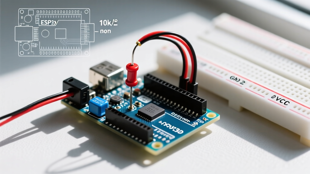
Solderless breadboards are notorious for intermittent connections. According to SparkFun's comprehensive multimeter guide, a pristine breadboard tie-point exhibits roughly 0.1Ω to 0.5Ω of contact resistance. However, after repeated insertion of thick component leads, this resistance can degrade to over 5Ω. When prototyping high-current paths (like motor drivers or LED matrices), use your meter's resistance mode to verify that the voltage drop across your breadboard jumper wires remains under 50mV under load. If it exceeds this, replace the jumper or move to a soldered perfboard.
Phase 2: Live Bus and Signal Validation
Once power is applied and the 'magic smoke' has been successfully contained, the next workflow step is verifying communication buses. A common mistake is assuming that an I2C or SPI peripheral is dead when, in reality, the bus is misconfigured at the hardware level.
I2C Pull-Up Verification
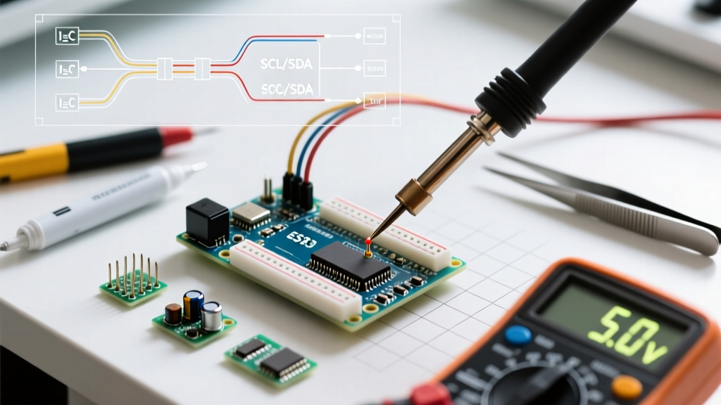
The I2C protocol requires pull-up resistors on both the SDA and SCL lines. Many Arduino-compatible sensors include onboard pull-ups, but some do not. Set your multimeter to DC Voltage mode. With the Arduino powered on but the I2C bus idle (no active scanning in your sketch), probe the SDA and SCL lines.
- Expected Reading: ~4.9V on a 5V system, or ~3.2V on a 3.3V system.
- Fault Reading (Floating): If you read 1.5V to 2.5V, your pull-up resistors are missing, damaged, or tied to the wrong voltage rail.
- Fault Reading (Stuck Low): If you read near 0V, a peripheral is holding the bus low, often indicating a damaged sensor or an incorrect wiring pinout.
UART and PWM Signal Averaging
While an oscilloscope is ideal for viewing PWM waveforms, a high-quality multimeter with a frequency or duty-cycle function can optimize your workflow for quick checks. If you are outputting a 50% duty cycle PWM signal at 490Hz (standard on Arduino Uno Pin 9), your multimeter's DC voltage mode should read approximately half of your logic high voltage (e.g., ~2.5V on a 5V system). This quick check confirms the ATmega328P is actually generating the signal before you waste time debugging the receiving motor driver circuitry.
Phase 3: Current Profiling and the 'Burden Voltage' Trap
For battery-powered IoT projects, optimizing deep sleep current is critical. This is where the Arduino multimeter workflow separates the amateurs from the experts. Measuring microamp (µA) sleep currents introduces a hidden variable that ruins countless debugging sessions: Burden Voltage.
Expert Insight: Burden voltage is the voltage dropped across the multimeter's internal shunt resistor when measuring current. If your meter drops 200mV on the mA range, and your ESP32 wakes from sleep drawing 80mA, the voltage supplied to the MCU drops below its Brown-Out Detector (BOD) threshold. The MCU resets, causing an infinite boot-loop. You will spend hours debugging 'bad code' when your multimeter is actually causing the crash.
Optimizing the Current Measurement Workflow
To accurately profile sleep current without inducing brown-outs, follow this protocol:
- Use the µA Range: Switch to the microamp range, which typically uses a higher-value shunt resistor but is designed for low-current draw. (Be aware that some cheap meters still introduce unacceptable voltage drops here).
- Parallel Capacitor Trick: Place a 100µF electrolytic capacitor in parallel with your multimeter probes. This capacitor supplies the instantaneous burst of current required when the MCU wakes up and transmits via Wi-Fi, bypassing the multimeter's shunt resistor and preventing the voltage sag that triggers a reset.
- Log the Data: As recommended in Fluke's guide on precision current measurement, use a meter with data-logging capabilities to capture the current spike profile over a 60-second sleep/wake cycle, rather than relying on the fleeting numbers on the LCD screen.
2026 Multimeter Comparison for MCU Workflows
Selecting the right tool is a core component of workflow optimization. Below is a comparison of three industry-standard multimeters evaluated specifically for microcontroller debugging in 2026.
| Model | Approx. Price (2026) | Continuity Speed | Burden Voltage (mA Range) | Best For |
|---|---|---|---|---|
| Fluke 117 | $215 | Ultra-Fast (<1ms) | Low (~1.8mV/mA) | Professional bench work, rapid short-finding |
| Brymen BM235 | $135 | Very Fast (<5ms) | Extremely Low | EEVblog favorite, deep sleep µA profiling |
| Uni-T UT61E+ | $85 | Moderate (~20ms) | Moderate | Budget makers, general voltage/resistance checks |
Edge Cases and Hardware Failure Modes
Even with a strict multimeter workflow, you will encounter edge cases that defy standard logic. Understanding these failure modes prevents unnecessary component replacement.
Ghost Voltages on Floating Pins
If you probe an unconfigured Arduino digital I/O pin and read 1.2V or 2.4V, do not assume the pin is damaged. Unconfigured pins are high-impedance (floating) and act as tiny antennas, picking up electromagnetic interference from your bench's AC mains wiring or nearby switching power supplies. Always configure unused pins as OUTPUT and set them LOW in your setup() function to eliminate ghost voltages and reduce parasitic power draw.
The Diode Test Mode for I/O Protection
Every ATmega328P and ESP32 I/O pin contains internal ESD protection diodes tied to VCC and GND. If you suspect you have fried a pin by over-volting it, set your multimeter to 'Diode Test' mode. With the Arduino unpowered, place the red probe on the VCC pin and the black probe on the suspect I/O pin. A healthy protection diode will read a forward voltage drop of roughly 0.5V to 0.7V. If it reads 'OL' (Open Loop) or 0.0V (Shorted), the internal silicon is destroyed, and you must move your wiring to a different physical pin or replace the microcontroller.
Summary: The CI/CD Approach to Hardware
Treat your Arduino multimeter workflow like a Continuous Integration/Continuous Deployment (CI/CD) pipeline for hardware. Just as you wouldn't merge code without passing unit tests, you should never upload a complex sketch without passing the Cold Verification, Bus Validation, and Current Profiling phases. By front-loading your hardware validation, you eliminate the 'ghost in the machine' scenarios that plague embedded development, ensuring that when your code fails, it is strictly a software issue. This paradigm shift is the single most effective optimization you can make to your electronics workbench.