
The Fundamentals of CAN Bus Arduino Communication
When building robust automotive, industrial, or robotics projects, standard protocols like I2C, SPI, or UART quickly reveal their limitations over long distances or in electrically noisy environments. Enter the Controller Area Network (CAN). Originally developed by Bosch in 1986 for automotive wiring harness reduction, CAN is a multi-master, message-broadcast protocol designed for extreme reliability. Integrating a CAN bus Arduino setup allows your microcontroller to communicate seamlessly with vehicle ECUs, industrial PLCs, and advanced motor controllers.
Unlike address-based protocols (like I2C) where a master polls specific slave addresses, CAN is message-based. Every node on the network receives every message, and each node decides whether to accept or ignore the data based on the message identifier. According to the Kvaser CAN Protocol Tutorial, this architecture eliminates the need for a central master, drastically reducing latency and single-point-of-failure risks.
Core Concepts: Differential Signaling and Arbitration
To understand why CAN is virtually immune to electromagnetic interference (EMI), you must understand its physical layer. CAN relies on differential signaling across two wires: CAN High (CAN_H) and CAN Low (CAN_L).
The Physics of the Signal
- Recessive State (Logic 1): Both CAN_H and CAN_L sit at approximately 2.5V. The differential voltage is 0V.
- Dominant State (Logic 0): CAN_H rises to ~3.5V, and CAN_L drops to ~1.5V. The differential voltage is 2.0V.
Because the receiver only looks at the difference between the two wires, any external noise induced equally onto both wires (common-mode noise) is mathematically canceled out. As detailed by Texas Instruments in their CAN transceiver design guides, this physical layer allows CAN to operate reliably at up to 1 Mbps over distances of 40 meters, and up to 125 kbps over 500 meters.
Non-Destructive Bitwise Arbitration
What happens if two Arduino nodes transmit at the exact same microsecond? CAN uses a wired-AND logic system. A dominant bit (0) physically overrides a recessive bit (1) on the bus. During the identifier phase of a message, if Node A transmits a recessive bit but reads back a dominant bit, it knows another node with a higher-priority message (lower numerical ID) is transmitting. Node A immediately stops transmitting and waits. Zero data is lost or corrupted during collisions.
Hardware Selection: Controllers vs. Transceivers
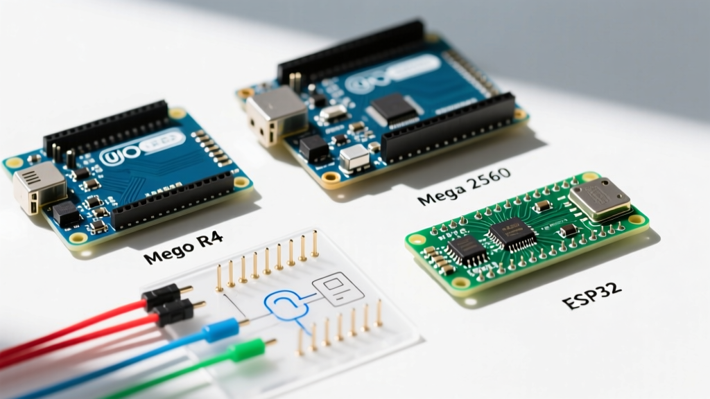
Most standard Arduino boards (Uno, Nano, Mega) lack a native CAN peripheral. To build a CAN bus Arduino network, you need two distinct pieces of hardware: a CAN Controller (which handles the protocol logic and message framing via SPI) and a CAN Transceiver (which converts the SPI logic levels into the differential physical signals).
| Configuration | Components | Logic Level | Avg. Cost | Best Use Case |
|---|---|---|---|---|
| Classic DIY Module | MCP2515 Controller + TJA1050 Transceiver | 5V | $3.50 - $5.00 | Arduino Uno/Mega, basic 500kbps networks |
| 3.3V Optimized Module | MCP2515 Controller + SN65HVD230 Transceiver | 3.3V | $4.00 - $6.00 | ESP8266, Teensy, 3.3V Pro Micros |
| Integrated Shield | Seeed Studio CAN-BUS Shield V2.0 | 5V | $19.95 | Rapid prototyping, OBD-II vehicle diagnostics |
| Native Peripheral | ESP32 (TWAI) + SN65HVD230 Transceiver only | 3.3V | $1.50 (Transceiver) | High-throughput IoT, ESP32-S3 native CAN |
Expert Warning: Never connect a 5V TJA1050 transceiver directly to a 3.3V microcontroller like the ESP32 without a logic level converter. While the ESP32 might survive briefly, the 5V logic will eventually degrade the GPIO pins. Always pair 3.3V MCUs with the SN65HVD230 or MCP2551 transceivers.
Wiring, Termination, and the 60-Ohm Rule
Wiring a CAN bus Arduino setup requires strict adherence to physical layer rules. The most common cause of CAN network failure in maker projects is improper termination and grounding.
The SPI Connection (MCP2515 to Arduino)
If you are using the ubiquitous MCP2515 module, it connects via SPI. For an Arduino Uno, the wiring is as follows:
- VCC: 5V
- GND: Ground
- CS (Chip Select): Pin 10 (or any digital pin, defined in software)
- SO (MISO): Pin 12
- SI (MOSI): Pin 11
- SCK: Pin 13
- INT (Interrupt): Pin 2 or 3 (Hardware interrupt pins)
Bus Termination and the Multimeter Test
A CAN bus must be terminated at both physical ends to prevent signal reflection, which causes data corruption. The standard characteristic impedance of CAN cabling is 120Ω. Therefore, you must place a 120Ω resistor between CAN_H and CAN_L at the first node, and another 120Ω resistor at the last node.
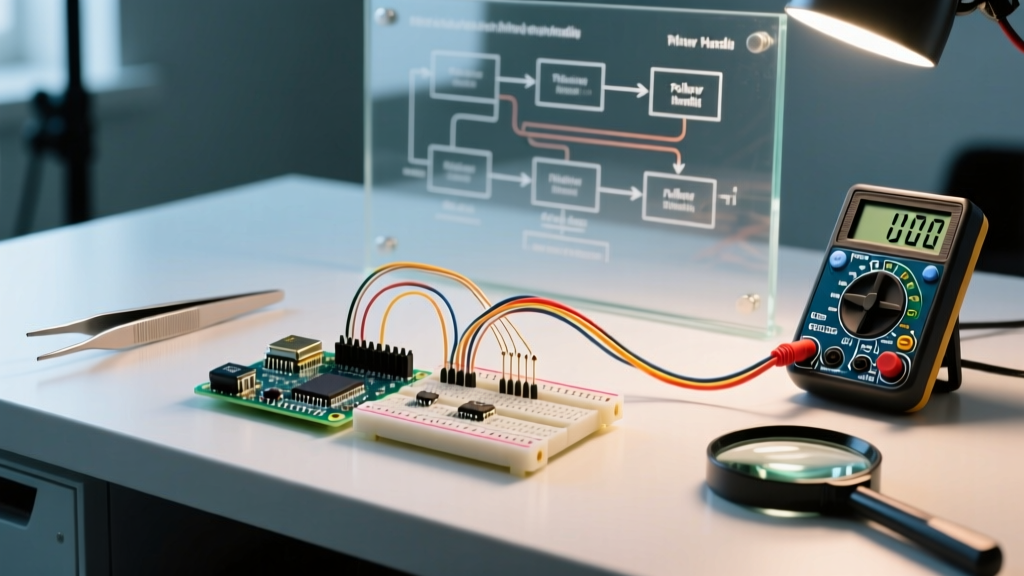
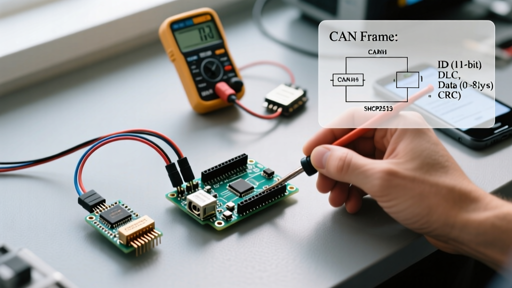
The 60-Ohm Test: With the power completely disconnected, use a digital multimeter to measure the resistance between CAN_H and CAN_L anywhere on the bus. Because the two 120Ω resistors are in parallel, your meter must read approximately 60Ω. If you read 120Ω, you are missing a terminator. If you read ~40Ω, you have too many terminators on the bus.
The Hidden Killer: Common Ground
While CAN is a differential 2-wire system, the transceivers still require a common ground reference to keep the common-mode voltage within their operating limits (typically ±12V for the Microchip MCP2515 and associated transceivers). If your Arduino is powered by a laptop in a car, and the car's ECU is grounded to the chassis, a ground potential difference of 15V will destroy the transceiver. Always run a third wire (Ground) alongside your CAN_H and CAN_L wires to tie the node grounds together.
Software: Message Framing and the mcp_can Library
On the software side, the industry standard for MCP2515 integration is the mcp_can library (originally by Cory Fowler). CAN messages consist of an Identifier (ID), a Data Length Code (DLC), and up to 8 bytes of payload data (in classic CAN 2.0B).
Standard vs. Extended Frames
- Standard Frame (CAN 2.0A): Uses an 11-bit identifier (0x000 to 0x7FF). Allows up to 2,048 unique message types.
- Extended Frame (CAN 2.0B): Uses a 29-bit identifier. Used heavily in J1939 heavy-duty vehicle standards and complex industrial networks.
Implementing Masks and Filters
Because every node receives every message, an Arduino processing 500 messages per second will quickly run out of CPU cycles if it has to parse every frame in software. The MCP2515 features hardware masking and filtering. By configuring the mask registers, you can instruct the controller to trigger an interrupt only when a specific ID (e.g., 0x1A4) arrives, ignoring all other bus traffic at the hardware level.
Troubleshooting Edge Cases and Failure Modes
Even with perfect wiring, CAN bus Arduino networks can enter error states. Understanding these states is critical for debugging.
1. The 'Bus-Off' State
CAN nodes maintain internal Transmit Error Counters (TEC) and Receive Error Counters (REC). If a node detects too many corrupted messages (usually due to a baud rate mismatch or missing termination), the TEC exceeds 255. The node enters the Bus-Off state and physically disconnects itself from the network to prevent flooding it with error frames. Fix: You must power-cycle the MCP2515 or send a specific software reset command to clear the error counters.
2. Baud Rate Drift
CAN requires strict timing. A standard 500 kbps network allows for a maximum bit-timing error of roughly 1%. If your Arduino is using an external ceramic resonator instead of a precision quartz crystal (common on cheap clone boards), temperature changes can cause clock drift, resulting in intermittent ACK (Acknowledgment) errors. Fix: Always use genuine Arduino boards or clones equipped with quartz crystals for CAN projects.
3. Oscilloscope Verification
If your code compiles but no data flows, hook up an oscilloscope. Trigger on CAN_H. You should see a clean square wave oscillating between 2.5V and 3.5V. If the signal looks like a jagged sawtooth or exhibits heavy ringing on the edges, your bus is unterminated, or your wiring stubs (the distance from the main bus line to your Arduino node) are too long. Keep stub lengths under 0.3 meters for 500 kbps networks.
Summary
Building a CAN bus Arduino network bridges the gap between hobbyist microcontrollers and industrial-grade communication. By respecting the physical layer—specifically the 60-ohm termination rule, common grounding, and correct transceiver voltage matching—you can create bulletproof networks capable of surviving the harshest electrical environments. Whether you are reverse-engineering a vehicle's OBD-II port or linking multiple ESP32s in a robotics chassis, mastering CAN is an essential skill for the modern maker.