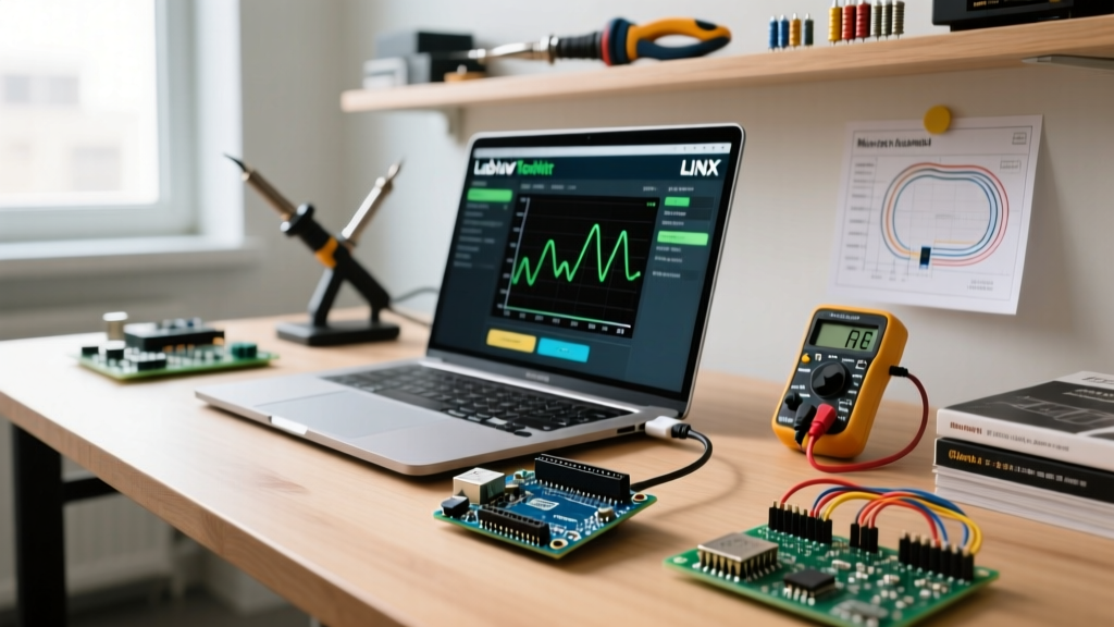

Mastering the Arduino and Joystick Interface
Integrating an analog joystick into a microcontroller project is a rite of passage for robotics, PTZ camera control, and RC vehicle builds. However, a surprising number of makers encounter erratic readings, axis drift, and blown GPIO pins when configuring their hardware. Configuring an Arduino and joystick properly goes far beyond simply calling analogRead(). It requires an understanding of ADC (Analog-to-Digital Converter) impedance, mechanical deadzones, and logic-level voltage tolerances.
In this comprehensive configuration guide, we will break down the wiring, hardware filtering, and software calibration required to achieve buttery-smooth, drift-free analog input using the most common modules on the market in 2026.
Hardware Selection Matrix: Which Module Fits Your Build?
Before writing a single line of code, you must select the right joystick topology for your MCU. Below is a comparison of the three most prevalent joystick modules used in the maker community today.
| Module Type | Interface | VCC / Logic | Avg. Price (2026) | Best Use Case |
|---|---|---|---|---|
| KY-023 Analog | Analog (2x) + Digital (1x) | 3.3V - 5V | $2.50 - $4.00 | Prototyping, basic RC cars, pan/tilt mounts |
| SparkFun Thumb Joystick (COM-09032) | Analog (2x) | 3.3V - 5V | $13.50 - $15.00 | High-reliability robotics, custom PCB integration |
| PS2 Wireless V2.0 | SPI (via 2.4GHz nRF24L01 clone) | 3.3V (Receiver) | $11.00 - $14.00 | Wireless RC rovers, drone remote controllers |
Wiring Configuration and the 3.3V Logic Trap
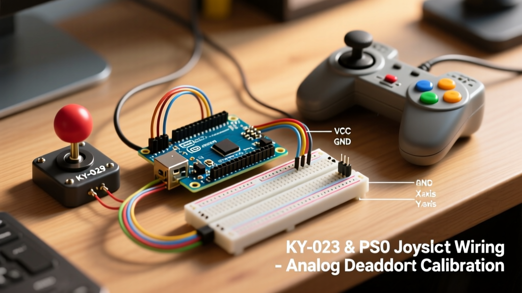
The ubiquitous KY-023 module features two 10kΩ potentiometers for the X and Y axes and a tactile push-button for the Z-axis (Select). While wiring the VRx and VRy pins to your Arduino's analog pins (e.g., A0 and A1) is straightforward, the SW (Select) pin is where most configurations fail.
The Pull-Up Resistor Hazard
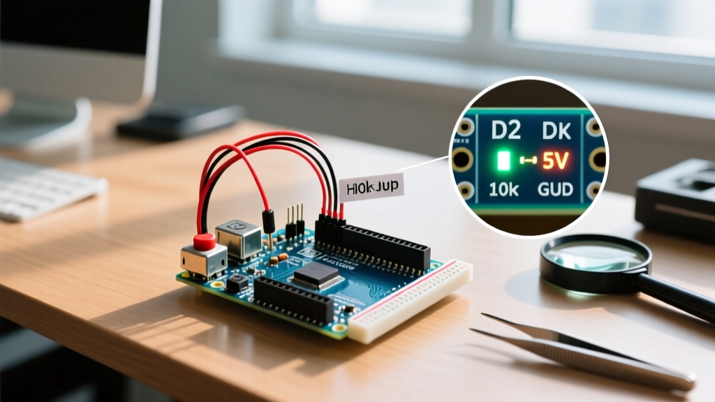
The KY-023 module includes a 10kΩ pull-up resistor on the SW pin tied directly to the VCC rail. When the joystick is not pressed, the SW pin outputs VCC. If you power the module with 5V and connect the SW pin to a 3.3V-tolerant GPIO on a modern board like the Arduino Portenta H7, Arduino Nano 33 BLE, or an ESP32, you will back-feed 5V into the silicon. Over time, this degrades the MCU's internal protection diodes and leads to permanent GPIO failure.
Configuration Rule of Thumb: If your MCU operates at 3.3V logic, power the KY-023 VCC pin with 3.3V. The analog readings will scale from 0-3.3V, which perfectly matches the 3.3V ADC reference of modern microcontrollers.
Taming ADC Jitter: The Hardware Filter Fix
When reading analog joysticks, makers frequently report 'jitter'—the ADC value bouncing between 510 and 514 even when the joystick is perfectly centered. This is not necessarily a defective potentiometer; it is an impedance mismatch issue.
According to the SparkFun Analog to Digital Conversion Guide, the internal sampling capacitor of an ATmega328P or SAMD21 ADC requires a low-impedance source to charge fully within the sampling window. The 10kΩ wiper resistance of a joystick, combined with long jumper wires acting as antennas, introduces high-frequency noise.
Implementing an RC Low-Pass Filter
To eliminate software-side oversampling overhead, add a 100nF (0.1µF) ceramic capacitor between the VRx analog output pin and GND. Repeat for VRy. This creates a passive RC low-pass filter.
- Resistance (R): 10,000Ω (Maximum potentiometer resistance)
- Capacitance (C): 0.0000001 F (100nF)
- Cutoff Frequency (fc): 1 / (2 × π × R × C) ≈ 159 Hz
Since human thumb movements rarely exceed 15 Hz, a 159 Hz cutoff perfectly preserves your input data while aggressively filtering out MCU switching noise and electromagnetic interference (EMI).
Software Configuration: Radial Deadzone Calibration
Mechanical potentiometers suffer from center-offset drift. A joystick at rest might read X: 518 and Y: 504 instead of a perfect 512. If you map these raw values directly to motor speeds, your robot will 'creep' when the joystick is untouched.
Furthermore, applying a square deadzone (clamping X and Y independently) results in unnatural diagonal movement. A radial deadzone calculates the vector magnitude from the center point, creating a circular zone of zero-output.
Arduino C++ Calibration Routine
Below is a production-ready configuration snippet utilizing the Arduino analogRead() Reference standards, enhanced with vector math for precise radial deadzone mapping.
// Joystick Pin Configuration
const int PIN_X = A0;
const int PIN_Y = A1;

// Calibration Constants (Measure these at rest)
const int X_CENTER = 518;
const int Y_CENTER = 504;
const int DEADZONE_RADIUS = 25; // Adjust based on mechanical slop

struct JoystickVector {
  float x;
  float y;
  float magnitude;
};

JoystickVector readCalibratedJoystick() {
  JoystickVector vec;

  // Read and center the raw 10-bit ADC values
  int rawX = analogRead(PIN_X) - X_CENTER;
  int rawY = analogRead(PIN_Y) - Y_CENTER;

  // Calculate radial magnitude using Pythagorean theorem
  vec.magnitude = sqrt((rawX * rawX) + (rawY * rawY));

  // Apply Radial Deadzone
  if (vec.magnitude < DEADZONE_RADIUS) {
    vec.x = 0.0;
    vec.y = 0.0;
    vec.magnitude = 0.0;
  } else {
    // Normalize to -1.0 to 1.0 range for motor/servo mixing
    // 512 is the max theoretical deviation from center
    vec.x = constrain((float)rawX / 512.0, -1.0, 1.0);
    vec.y = constrain((float)rawY / 512.0, -1.0, 1.0);
  }

  return vec;
}
Configuring the PS2 Wireless Joystick (SPI Setup)
If your project requires wireless operation, the PS2 Wireless Joystick V2.0 is the standard. The receiver module utilizes a BK2423 chip (a clone of the Nordic nRF24L01). Configuring this requires strict adherence to SPI bus rules.
- Power: The receiver module must be powered by 3.3V. Connecting it to 5V will instantly destroy the RF transceiver.
- SPI Pins: Wire MOSI to Pin 11, MISO to Pin 12, and SCK to Pin 13 (on standard Arduino Uno/Nano).
- Chip Select (CSN) & Chip Enable (CE): Assign CSN to Pin 10 and CE to Pin 9. Ensure these are configured as
OUTPUTin yoursetup()loop before initializing the RF24 library. - Capacitive Buffer: The nRF24L01 draws sharp current spikes (up to 15mA) during transmission. Solder a 10µF electrolytic capacitor directly across the VCC and GND pins of the receiver module to prevent brownout resets on your Arduino's 3.3V voltage regulator.
Troubleshooting Edge Cases and Failure Modes
Even with perfect wiring, environmental and mechanical factors can disrupt your configuration. Use this diagnostic checklist when your Arduino and joystick setup behaves erratically.
- Inverted Axes: If pushing 'Up' yields a negative value, do not rewrite your math. Simply swap the physical VRx and VRy wires on your breadboard, or invert the mapping in software by subtracting the raw read from 1023.
- Ghosting / Crosstalk: If moving the X-axis slightly alters the Y-axis reading, you are experiencing ADC crosstalk. This happens when the ADC sampling capacitor retains charge from the previous pin read. Fix: Read the analog pin twice in succession and discard the first value. Alternatively, consult the Arduino Built-In Smoothing Example to implement a rolling average array.
- Button Bounce on SW Pin: The tactile switch on the KY-023 is notoriously noisy. Configure your software to use a 50-millisecond debounce delay, or utilize the
Bounce2library to handle state changes cleanly without blocking your main control loop. - Non-Linear Taper: Cheap potentiometers use a linear taper, but human perception is logarithmic. If your RC car accelerates too aggressively in the first 20% of stick movement, apply a cubic mapping function (
output = input * input * input) to your normalized vector to create a more natural, exponential throttle curve.
Final Configuration Takeaways
Successfully pairing an Arduino and joystick relies on respecting the physics of the hardware. By protecting your 3.3V logic pins, implementing passive RC filtering to stabilize the ADC, and utilizing a radial deadzone in your C++ code, you elevate a jittery prototype into a responsive, professional-grade control interface. Whether you are building a robotic arm or a wireless rover, these configuration principles will ensure your inputs are as precise as your mechanics.