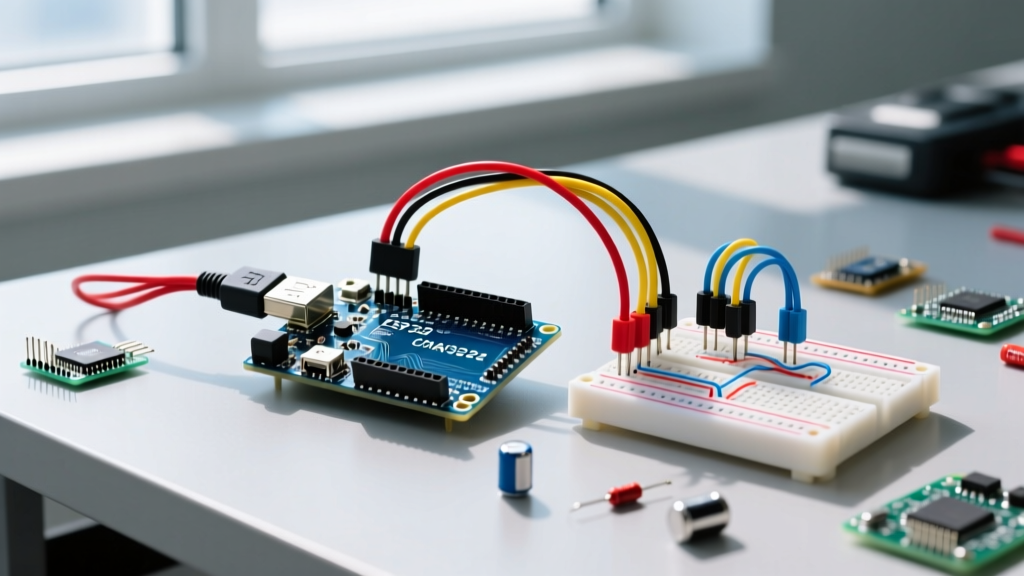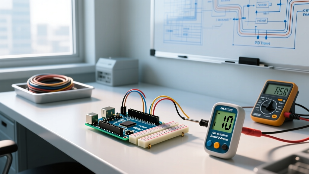

Why Use an Arduino for Temperature Control?
Basic on/off (bang-bang) thermostats are sufficient for home HVAC systems, but they fail miserably in precision applications like 3D printer hotends, chemical reactors, or sous-vide cooking. When your application demands stability within ±0.5°C, you need Proportional-Integral-Derivative (PID) logic. Using an Arduino for temperature control allows you to implement a closed-loop PID system that continuously calculates an error value and applies a dynamic correction to a heating element via a Solid State Relay (SSR).
In this 2026 guide, we will build a 120V AC heater control system using an Arduino Uno R4 Minima, a K-type thermocouple, and the industry-standard PID_v1 library. We will cover hardware selection, wiring, coding, and the Ziegler-Nichols tuning method to eliminate thermal overshoot.
Hardware Bill of Materials (BOM) & Costs
To build a reliable and safe system, avoid cheap, unbranded components. The market is currently flooded with counterfeit SSRs that fail in a closed (shorted) state, leading to catastrophic thermal runaway. Below is the recommended BOM for a safe, precision build.
- Microcontroller: Arduino Uno R4 Minima ($27.50) - Chosen for its 12-bit ADC and enhanced processing speed over the legacy R3.
- Sensor Amplifier: Adafruit MAX31856 Thermocouple Amplifier ($19.95) - Superior to the older MAX6675 due to 19-bit resolution and 50/60Hz noise rejection.
- Probe: K-Type Thermocouple with Stainless Steel Braid ($14.00) - Rated up to 400°C.
- Switching Component: Genuine Omron G3NA-210B SSR ($24.00) - Zero-cross switching, 10A rating, built-in snubber circuit.
- Heater: 120V 300W Cartridge Heater ($32.00) - High watt density for rapid thermal response.
- Safety: 10A DIN-mount fuse holder and 10A glass fuse ($8.50).
Total Estimated Cost: ~$125.95
Sensor Amplifier Comparison: MAX6675 vs MAX31856
Many legacy tutorials recommend the MAX6675. However, for modern precision applications, the MAX31856 is the superior choice. According to NIST Sensor Science guidelines on thermocouples, proper cold junction compensation and noise rejection are critical for accurate high-temperature readings.
| Feature | MAX6675 (Legacy) | MAX31856 (Recommended) |
|---|---|---|
| Resolution | 12-bit (0.25°C) | 19-bit (0.0078°C) |
| Thermocouple Types | K-Type Only | All Standard Types (B, E, J, K, N, R, S, T) |
| Noise Rejection | None | 50Hz/60Hz Switchable Filter |
| Fault Detection | Open Circuit Only | Open, Short, Over/Under Voltage |
Wiring and Pinout Configuration
The MAX31856 communicates via SPI, while the SSR requires a simple digital PWM or digital output signal. Because the Arduino PID library outputs a time-proportioned signal (not true analog PWM), we will use a standard digital pin for the SSR.
| Component | Pin | Arduino Uno R4 Pin |
|---|---|---|
| MAX31856 | SDI (MISO) | D12 |
| MAX31856 | SDO (MOSI) | D11 |
| MAX31856 | SCK | D13 |
| MAX31856 | CS | D10 |
| MAX31856 | VIN | 5V |
| MAX31856 | GND | GND |
| Omron SSR | Input (+) | D3 (PWM capable) |
| Omron SSR | Input (-) | GND |
Safety Warning: Never wire the 120V AC mains directly to the Arduino. The SSR acts as an optical isolator, keeping the high-voltage AC side completely electrically isolated from the low-voltage DC microcontroller side. Always enclose mains wiring in a grounded, fireproof project box.
Step 1: Implementing the PID Logic
To handle the complex calculus required for PID, we use the PID_v1 library, extensively documented on the Arduino Playground PID Library page. The library requires three variables: Input (current temperature), Setpoint (target temperature), and Output (the time-proportioned signal sent to the SSR).
Core Sketch Structure
#include <Adafruit_MAX31856.h>
#include <PID_v1.h>

// Thermocouple setup
Adafruit_MAX31856 max = Adafruit_MAX31856(10, 11, 12, 13);

// PID Variables
double Setpoint, Input, Output;
double Kp=400, Ki=0.2, Kd=0.1; // Initial tuning parameters
int WindowSize = 1000; // 1 second time-proportioning window
unsigned long windowStartTime;

PID myPID(&Input, &Output, &Setpoint, Kp, Ki, Kd, DIRECT);

void setup() {
  Serial.begin(115200);
  max.begin();
  max.setThermocoupleType(MAX31856_TCTYPE_K);

  Setpoint = 150.0; // Target 150°C
  myPID.SetOutputLimits(0, WindowSize);
  myPID.SetMode(AUTOMATIC);
  windowStartTime = millis();
}

void loop() {
  // Read Temperature
  Input = max.readThermocoupleTemperature();

  // Thermal Runaway Protection
  if (Input > 250.0 || isnan(Input)) {
    Output = 0; // Force heater off if sensor fails or exceeds safe limit
    digitalWrite(3, LOW);
    Serial.println('FAULT: Heater Disabled');
    return;
  }

  myPID.Compute();

  // Time-Proportioning Output to SSR
  unsigned long now = millis();
  if (now - windowStartTime > WindowSize) {
    windowStartTime += WindowSize;
  }
  if (Output > now - windowStartTime) {
    digitalWrite(3, HIGH);
  } else {
    digitalWrite(3, LOW);
  }
}
Step 2: Tuning the PID Controller (Ziegler-Nichols Method)
Out-of-the-box PID values will rarely work for your specific heater and thermal mass. A 300W heater acting on a small aluminum block will overshoot wildly compared to the same heater acting on a liter of water. We use the Ziegler-Nichols method to find the optimal Kp, Ki, and Kd values.
The Tuning Procedure
- Disable I and D: Set
KiandKdto 0 in your code. - Increase P: Start with a low
Kp(e.g., 100) and increase it in increments of 50 while the system is running. - Find Ultimate Gain (Ku): Watch the Serial Plotter. You are looking for the exact
Kpvalue where the temperature begins to oscillate steadily above and below the setpoint. Record this value as Ku. - Measure Period (Tu): Measure the time (in seconds) between the peaks of the oscillation. This is Tu.
- Calculate Final Values: Apply the standard Ziegler-Nichols formulas:
Kp= 0.6 * KuKi= 1.2 * Ku / TuKd= 3 * Ku * Tu / 40
Pro-Tip: If your system oscillates too aggressively even after tuning, halve the Kp value. In thermal systems, derivative (D) kick can occur if the sensor picks up electrical noise from the SSR switching. Ensure your thermocouple wires are routed away from the AC mains lines to prevent inductive coupling.
Edge Cases and Failure Modes
When deploying an Arduino for temperature control in real-world environments, you must account for hardware failure modes that software alone cannot fix.
1. SSR Short-Circuit Failure
Solid State Relays typically fail 'closed' (shorted) when subjected to current spikes or inadequate heat sinking. If the Omron SSR fails shorted, the Arduino loses all control, and the heater will remain on indefinitely. Solution: Always install a physical, mechanical thermal fuse (rated slightly above your max setpoint, e.g., 180°C for a 150°C system) in series with the heater's AC line. This provides a hardware-level fail-safe that melts and breaks the circuit if software control is lost.
2. Thermocouple Grounding Loops
If your K-type thermocouple probe is physically touching a grounded metal chassis (like an aluminum heater block that is earth-grounded), and the MAX31856 is also grounded via the Arduino's USB shield, you can create a ground loop. This introduces 50/60Hz noise into the SPI reading, causing the PID to react to phantom temperature spikes. Solution: Use an ungrounded (isolated) thermocouple probe, or implement software-based moving average filtering on the Input variable before passing it to myPID.Compute().
3. Integral Windup
If the heater is physically incapable of reaching the setpoint (e.g., Setpoint is 300°C, but the 300W heater maxes out at 260°C due to poor insulation), the Integral (Ki) term will accumulate massive error over time. When you finally lower the setpoint to 200°C, the accumulated integral error will force the heater to stay on 100% until the 'debt' is paid off, causing massive overshoot. Solution: The PID_v1 library handles this via SetOutputLimits, but you should also implement a physical insulation jacket around your heating block to ensure the heater has the thermal authority to reach your target.
Conclusion
Building a closed-loop system using an Arduino for temperature control bridges the gap between amateur maker projects and industrial-grade process control. By investing in a genuine Omron SSR, utilizing the high-resolution MAX31856 amplifier, and rigorously applying the Ziegler-Nichols tuning method, you can achieve laboratory-grade thermal stability. Always prioritize hardware fail-safes like thermal fuses to ensure your project remains safe under all edge-case conditions.