
Mastering the Breadboard for Arduino Projects
Building circuits on a solderless breadboard is the foundational skill for any maker working with microcontrollers. However, a poorly wired breadboard for Arduino projects is the leading cause of debugging nightmares, floating pins, and mysterious resets. Whether you are using a classic Arduino Uno R3 or the modern Arduino Uno R4 WiFi, understanding the physical and electrical realities of prototyping boards is critical. In 2026, a high-quality 830-point breadboard like the Busboard BB830 or Elegoo BB400 typically costs between $6 and $9, making it an accessible but unforgiving medium if used incorrectly. This step-by-step tutorial will guide you through professional wiring techniques, edge-case troubleshooting, and high-frequency limitations.
Anatomy of a Standard 830-Point Breadboard
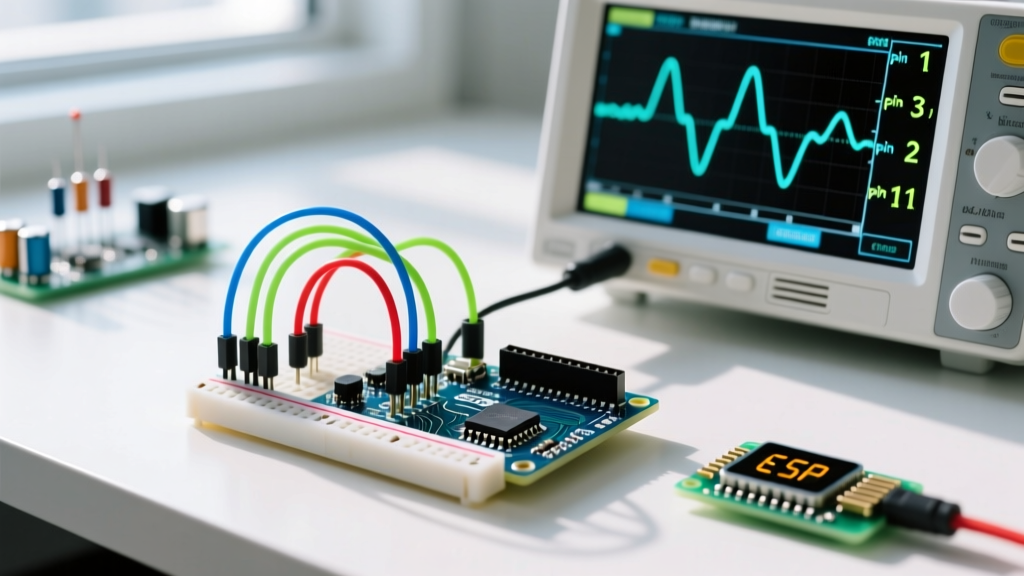
Before routing your first jumper wire, you must understand the internal topology of the board. According to SparkFun's comprehensive breadboard guide, a standard 830-point board is divided into three main sections:
- Terminal Strips (630 tie points): The central area containing 63 rows of 5 holes each. Internally, these 5 holes are connected by a metal leaf-spring clip.
- Power Rails (200 tie points): The four outer columns (marked with red and blue lines) that run the length of the board. These are internally connected vertically.
- The Center Trench: A physical gap separating the left and right terminal strips, designed specifically to allow Dual In-line Package (DIP) integrated circuits to straddle the center without shorting opposing pins.
Step 1: Establishing the Power Rails (and Avoiding the Split-Rail Trap)
The most common mistake beginners make when setting up a breadboard for Arduino is assuming the power rails are continuous from top to bottom. On most full-size 830-point boards, the power rails are split in the middle (usually around row 30). There is a physical gap in the internal metal clip to allow you to run two different voltage domains (e.g., 5V on the top half, 3.3V on the bottom half).
Critical Warning: If you plug your Arduino 5V pin into the top-left red rail and your sensor ground into the bottom-left blue rail without bridging the middle gap, your circuit will not have a common ground. Always use a short jumper wire to bridge the red-to-red and blue-to-blue rails across the center divide before powering on.
Connecting the Arduino
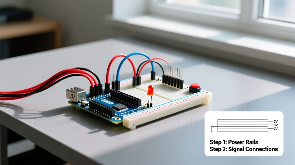
- Connect a red 22 AWG solid-core jumper wire from the Arduino's 5V pin to the left red power rail.
- Connect a black jumper wire from the Arduino's GND pin to the left blue power rail.
- Bridge the split rails using additional red and black jumpers if your components span the entire length of the board.
Note on Arduino Uno R4 Power Limits: The newer Arduino Uno R4 WiFi and Minima boards have stricter current limits on the 5V pin when powered via USB (typically capped around 500mA). If your breadboard circuit includes high-draw components like LED matrices or multiple servos, power the breadboard rails using an external bench power supply, ensuring you tie the external supply's ground to the Arduino's ground.
Step 2: Stripping and Inserting Jumper Wires
The physical preparation of your wires dictates the reliability of your breadboard for Arduino connections. Pre-cut, pre-stripped jumper wire kits (often sold in rainbow spools for $5 to $8) are convenient, but cutting your own wire from a spool of 22 AWG solid-core copper offers superior routing and troubleshooting clarity.
The 1/4-Inch Stripping Rule
Strip exactly 1/4 inch (6mm) of insulation from the wire ends. The internal clips of a breadboard are designed to grip 20 to 24 AWG wire. If you strip too much insulation, bare copper will sit above the plastic housing, risking accidental short circuits when you adjust components. If you strip too little, the wire's insulation will bottom out on the plastic housing before the copper makes contact with the internal leaf spring, resulting in an open circuit.
Never use stranded wire for breadboard jumpers. Stranded wire frays upon insertion, leaving microscopic copper splinters that bridge adjacent rows, causing phantom short circuits that are nearly impossible to see.
Step 3: Straddling the Center Trench with ICs and Modules
When placing DIP ICs (like the ATmega328P, L293D motor driver, or 74HC595 shift registers), they must straddle the center trench. The trench aligns perfectly with the standard 0.3-inch (7.62mm) width of DIP chips. Push the IC down firmly using even pressure on both sides. If you press too hard on one side, you will bend the internal pins underneath the plastic body, ruining the chip and the breadboard contacts.
For breakout boards and Arduino shields with male header pins, ensure the pins are fully seated. A partially inserted I2C sensor module (like a BME280 or MPU6050) will result in intermittent SDA/SCL connections, causing the Arduino Wire library to hang indefinitely during the Wire.endTransmission() call.
Step 4: Routing Signals and Adding Pull-Up Resistors
Microcontroller pins are highly sensitive to floating states. When wiring buttons, switches, or open-drain sensors to your breadboard for Arduino, you must define the logic level when the switch is open.
- Pull-Down Resistor: Connect a 10kΩ resistor between the signal pin and the GND rail. The switch connects the signal pin to 5V. (Default state: LOW).
- Pull-Up Resistor: Connect a 10kΩ resistor between the signal pin and the 5V rail. The switch connects the signal pin to GND. (Default state: HIGH). This is the preferred method, as the Arduino's internal microcontroller has built-in pull-up resistors that can be activated via
pinMode(pin, INPUT_PULLUP), often eliminating the need for external breadboard resistors entirely.
For I2C communication (SDA/SCL lines), external pull-up resistors are mandatory. Use 4.7kΩ resistors for standard 100kHz I2C, and drop to 2.2kΩ resistors if you are pushing Fast-Mode 400kHz I2C across long breadboard jumper runs.
Troubleshooting Matrix: Common Breadboard Failures
Even with perfect technique, breadboards degrade over time. The internal leaf springs lose tension, and oxidation builds up. Use this diagnostic matrix when your Arduino sketch fails to behave as expected.
| Symptom | Root Cause | Solution |
|---|---|---|
| Arduino randomly resets when a motor/relay triggers. | Voltage brownout on the breadboard power rail due to high transient current draw and thin jumper wires. | Add a 100µF electrolytic decoupling capacitor directly across the power rails near the motor driver. Use thicker 20 AWG wires for power. |
| I2C sensor returns 0xFF or hangs the sketch. | Missing pull-up resistors on SDA/SCL, or parasitic capacitance from long breadboard traces slowing edge transitions. | Add 4.7kΩ pull-ups to 5V. Keep I2C jumper wires under 6 inches. Verify common ground. |
| LED glows dimly or flickers when touched. | High contact resistance in worn-out breadboard clips; wire is not fully seated. | Move the component to a fresh, unused row on the terminal strip. Replace the breadboard if clips are permanently stretched. |
| ADC (AnalogRead) values are noisy and jumping. | Floating analog pins or lack of a bypass capacitor near the sensor output. | Add a 0.1µF ceramic capacitor between the analog signal line and GND to filter high-frequency breadboard noise. |
High-Frequency Limits: When to Abandon the Breadboard
While a breadboard for Arduino is perfect for low-speed digital I/O, PWM, and basic analog sensing, it is fundamentally hostile to high-frequency signals. Every metal-to-metal contact point and parallel wire run on a breadboard introduces 2pF to 5pF of parasitic capacitance. Furthermore, the long, looped jumper wires act as inductors and antennas, picking up electromagnetic interference (EMI).
As detailed in advanced prototyping guidelines from Adafruit's breadboarding tutorials, you will hit a physical wall when attempting:
- SPI Communications above 10 MHz: Signal reflections and capacitive loading will corrupt data packets between the Arduino and high-speed SPI displays or SD card modules.
- Fast-Mode Plus I2C (1 MHz): The RC time constant created by parasitic capacitance and pull-up resistors will prevent the signal lines from reaching logic HIGH thresholds in time.
- Audio / RF Signals: High-fidelity audio DAC outputs or RF transmitter modules (like the nRF24L01 at 2.4 GHz) will suffer severe signal degradation and cross-talk.
When your project demands these high-speed protocols, it is time to migrate from the breadboard to a custom Printed Circuit Board (PCB) or a dedicated soldered perfboard with a ground plane.
Conclusion
Wiring a breadboard for Arduino is an exercise in physical discipline as much as electrical engineering. By respecting the split-rail topology, stripping wires to exact measurements, managing pull-up resistors, and understanding the parasitic limits of solderless contacts, you will eliminate 90% of the hardware bugs that plague beginner projects. Keep your power rails bridged, your grounds common, and your jumper wires short, and your microcontroller prototypes will run flawlessly.
For further reading on foundational electronics prototyping, refer to the official Arduino Breadboard Foundations guide to deepen your understanding of circuit topologies.