
The Core Bottleneck in Force Sensing Workflows
Integrating force sensors into microcontroller projects is a common requirement for robotics, MIDI controllers, and industrial scales. However, the standard analogRead() workflow taught in beginner tutorials is fundamentally flawed for production environments. It ignores non-linearity, thermal drift, and electromagnetic interference (EMI). As of 2026, while component availability has stabilized and prices for precision ADCs have dropped, developers still lose weeks debugging noisy data and hysteresis issues.
This guide optimizes your force sensors Arduino workflow by forcing a critical decision early: choosing between Force Sensitive Resistors (FSRs) and Strain Gauge Load Cells. We will cover hardware signal conditioning, software linearization, and edge-case mitigation to cut your development time in half.
Decision Matrix: FSR vs. Load Cell Integration
Choosing the wrong sensor type is the primary cause of project failure. FSRs are cheap and flexible but highly non-linear. Load cells are rigid and require amplification but offer laboratory-grade precision. Use the matrix below to select the right component for your specific workflow.
| Metric | FSR (e.g., Interlink 402) | Load Cell + HX711 (e.g., SparkFun 50kg) |
|---|---|---|
| Cost (2026 Avg) | $12.00 - $16.00 | $14.00 - $19.00 (Sensor + Amp) |
| Measurement Range | 10g to 10kg (Dynamic) | 1kg to 500kg (Static/Dynamic) |
| Linearity | Poor (Inverse exponential) | Excellent (<0.05% FSO) |
| Hysteresis | 5% - 10% | <0.1% |
| Wiring Complexity | Low (Voltage Divider) | Medium (Wheatstone Bridge + Amp) |
| Best Use Case | Touch detection, MIDI, grips | Scales, tensioning, robotic feedback |
Hardware Workflow: Signal Conditioning & Wiring
Skip the direct-to-pin wiring. Raw sensor signals are highly susceptible to 50/60Hz mains hum and RF interference. Optimizing your hardware layer ensures your software layer doesn't have to overcompensate.
Optimizing the FSR Voltage Divider
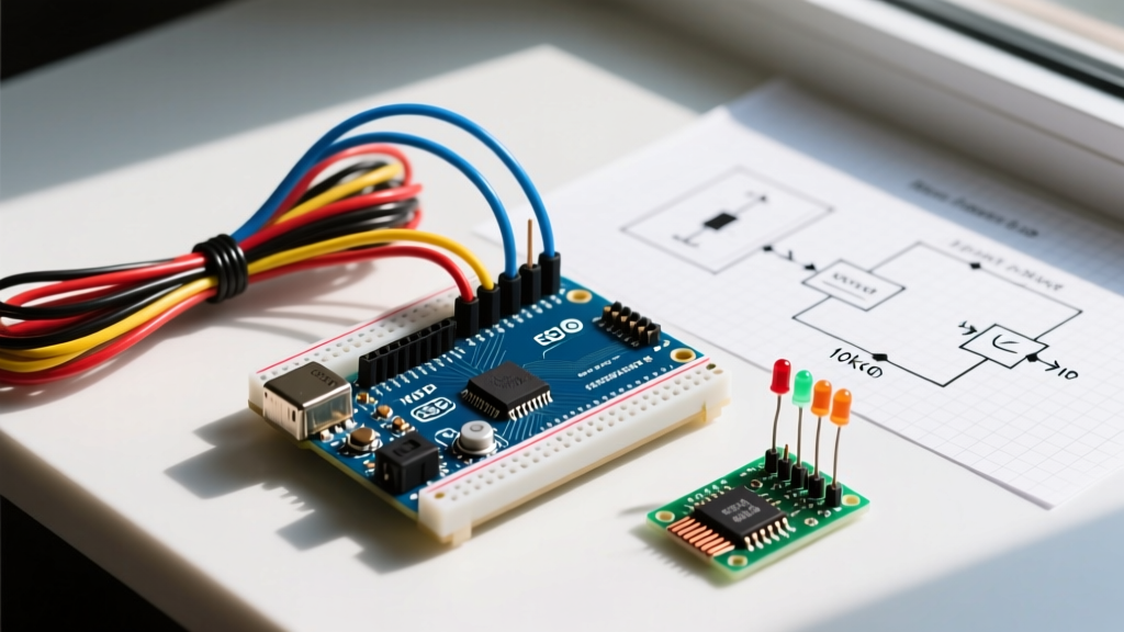
An FSR acts as a variable resistor. To read it with an Arduino's 10-bit ADC, you must build a voltage divider. The standard tutorial suggests a 10kΩ pulldown resistor. However, for optimized sensitivity in the 1N to 5N range (typical for human-interface devices), a 3.3kΩ or 4.7kΩ pulldown shifts the steep part of the voltage curve into your target operating window.
- Hardware Low-Pass Filter: Solder a 100nF (0.1µF) ceramic capacitor directly between the analog wiper pin and ground. Combined with a 10kΩ pulldown, this creates an RC filter with a cutoff frequency of ~160Hz, instantly eliminating high-frequency EMI before it reaches the ADC.
- ADC Reference: Power the FSR divider from the Arduino's 3.3V or 5V pin, but use the
analogReference(DEFAULT)or an external precision reference if your board's USB voltage sags under load.
For deep hardware integration details, consult the SparkFun FSR Hookup Guide, which provides excellent baseline circuit schematics for various microcontroller logic levels.
HX711 Load Cell Wiring and Gain Staging
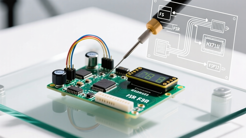
The HX711 remains the undisputed budget king for load cell amplification in 2026, though newer I2C alternatives like the NAU7802 are gaining traction for multi-sensor arrays. When wiring the HX711:
- Keep the E+, E-, A+, A- wires from the load cell to the HX711 as short as possible (under 15cm) to prevent the wires from acting as antennas.
- Use twisted pair cables if the distance must exceed 15cm.
- Gain Staging: The HX711 Channel A offers 128x or 64x gain. Channel B is fixed at 32x. For standard 2mV/V load cells powered by 5V, Channel A at 128x gain is mandatory to utilize the full 24-bit resolution.
Software Workflow: Calibration and Data Linearization
Raw data is useless. Your software workflow must account for the physical realities of the sensor material.
Beating Non-Linearity with Polynomial Regression
FSRs do not output a linear voltage-to-force curve. Their conductance (1/R) is roughly linear with force, but the voltage read by the Arduino is not. Instead of using the map() function which assumes linearity, implement a 2nd-order polynomial regression.
Collect three calibration points using known weights (e.g., 100g, 500g, 1000g). Record the raw ADC values. Use a spreadsheet to generate a polynomial trendline equation: Force = a(ADC^2) + b(ADC) + c. Hardcode these coefficients into your Arduino sketch. This single step reduces FSR measurement error from ~25% down to <5% across the operating range.
Digital Filtering for Noisy ADC Readings
Even with hardware RC filters, mechanical vibrations will cause ADC jitter. Replace simple averaging with an Exponential Moving Average (EMA) or a Moving Median filter.
- EMA:
filteredValue = (alpha * rawValue) + ((1 - alpha) * filteredValue);where alpha is between 0.05 and 0.2. This requires minimal RAM and responds smoothly to gradual force changes. - Moving Median: Best for eliminating sudden, massive spike outliers (like a physical bump to the chassis) without lagging the true signal. Store the last 5 readings in an array, sort them, and return the middle value.
For comprehensive load cell calibration code and tare logic, the SparkFun HX711 Breakout Hookup Guide provides robust library examples that handle the 24-bit two's complement data conversion automatically.
Edge Cases: Hysteresis, Creep, and Thermal Drift
To build a truly reliable system, you must code around the physical limitations of your chosen sensor.
FSR Creep and Hysteresis
FSRs suffer from 'creep'—if you apply a constant 5kg load, the resistance will slowly drift downward over 10-20 minutes, making the Arduino read an increasing force. They also exhibit hysteresis; the reading when force is increasing to 5kg will differ from when force is decreasing to 5kg.
Workflow Fix: Never use FSRs for static, long-term weight measurement. Use them only for dynamic, transient events (e.g., detecting a footstep or a drum strike). If you must hold a state, implement a software 'tare' routine that resets the baseline every time the sensor reads below a 50g threshold for more than 2 seconds.
Load Cell Thermal Drift
Strain gauges are temperature-sensitive. A 10°C shift in ambient room temperature can cause a 50kg load cell to drift by 50-100 grams. Furthermore, the HX711 chip itself generates a small amount of heat which can affect the immediate vicinity if mounted too close to the load cell body.
Workflow Fix: Mount the HX711 at least 10cm away from the physical load cell. If your environment experiences wide temperature swings, implement a software auto-tare function that triggers during known 'empty' states, or integrate a digital temperature sensor (like the BME280) to apply a thermal compensation offset in your code.
Summary Checklist for Production Deployment
Before finalizing your force sensors Arduino project, verify the following optimization checkpoints:
- [ ] Sensor Match: FSR selected for dynamic/touch; Load Cell selected for static/precision.
- [ ] Hardware Filter: 100nF capacitor installed on FSR analog wiper.
- [ ] Wiring: Load cell wires kept under 15cm; HX711 gain set to 128.
- [ ] Linearization: Polynomial regression applied to FSR data; HX711 calibration factor calculated using known physical weights.
- [ ] Software Filter: EMA or Moving Median implemented to smooth mechanical jitter.
- [ ] Edge Cases: Auto-tare logic programmed to combat FSR creep and Load Cell thermal drift.
By shifting your focus from basic analog reading to comprehensive signal conditioning and mathematical linearization, you transform unreliable prototype data into robust, production-ready force measurements. For further reading on strain gauge physics and advanced temperature compensation techniques, review the technical resources provided by Adafruit's FSR and Sensor Learning System.