
Why the L293D Fails in Modern Arduino Projects
Connecting an L293D to Arduino microcontrollers is a foundational rite of passage for robotics enthusiasts. However, the Texas Instruments L293D (and its SN754410NE cousin) is a legacy bipolar H-bridge design. While it remains incredibly popular due to its low cost (typically $1.50 to $2.50 for a DIP-16 package in 2026), its internal architecture introduces specific failure modes that modern MOSFET-based drivers do not suffer from. If your DC motors are stuttering, the chip is burning your fingers, or your PWM speed control is entirely unresponsive, the issue usually stems from a misunderstanding of its internal Darlington transistor pairs and strict power isolation requirements.
Expert Insight: The most frequent reason makers abandon a working circuit is the L293D's internal voltage drop. Because it uses bipolar junction transistors (BJTs) rather than MOSFETs, you lose approximately 1.4V to 2V across the internal H-bridge. If you supply 5V to the motor power pin, your motor only receives ~3.6V. Always measure voltage at the motor terminals, not the battery pack, when diagnosing 'weak' motors.
Pinout Verification: The Most Common Wiring Traps
The L293D features a 16-pin DIP package that is notoriously easy to wire incorrectly on a solderless breadboard. Before replacing a 'dead' chip, verify these critical nodes with a digital multimeter (DMM).
VCC1 vs. VCC2 Power Isolation
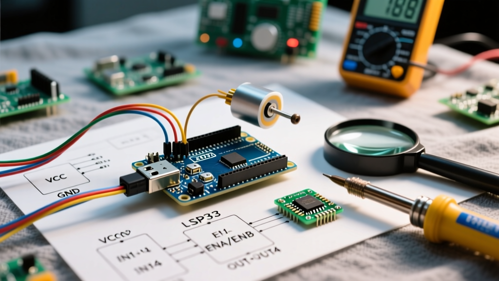
The L293D requires two separate power sources to protect the Arduino's sensitive logic circuits from motor back-EMF and voltage sag:
- Pin 16 (VCC1): Logic power. Must be tied directly to the Arduino's 5V output. Do not exceed 7V.
- Pin 8 (VCC2): Motor power. Connect this to your external battery pack (e.g., 4x AA batteries for 6V, or a 2S LiPo for 7.4V). The absolute maximum rating is 36V, but practical thermal limits keep most makers under 12V.
- Pins 4, 5, 12, 13 (GND): All four ground pins must be tied to a common ground shared with the Arduino and the battery pack. Missing even one ground pin increases internal resistance and triggers thermal shutdown.
The Thermal Shutdown Threshold
According to the Texas Instruments L293D Datasheet, the chip features internal thermal shutdown that activates when the junction temperature reaches 150°C. Because the chip dissipates roughly 1.2W of heat per channel at its 600mA continuous limit, the DIP-16 package will become too hot to touch within 30 seconds of stall-current conditions. If your motor runs for ten seconds and then abruptly stops, the chip has thermally throttled. You must either add a PCB heatsink to the ground pins, reduce the mechanical load, or upgrade to a modern driver.
Diagnostic Matrix: Symptoms, Tests, and Fixes
Use this structured troubleshooting matrix to isolate your specific L293D to Arduino fault. Set your multimeter to DC Voltage mode and probe the specified pins while the Arduino sketch is running.
| Symptom | Multimeter Test Point | Expected Reading | Root Cause & Actionable Fix |
|---|---|---|---|
| Motor twitches but won't spin | VCC2 (Pin 8) to GND | Matches Battery Voltage | Voltage sag under load. The battery cannot supply the stall current. Upgrade to a higher C-rating LiPo or add a 470µF decoupling capacitor across VCC2 and GND. |
| Motor spins in one direction only | IN1 & IN2 (Pins 2 & 7) | 5V / 0V alternating | Faulty breadboard contact on one logic pin, or a blown internal half-bridge. Swap IN1/IN2 wires; if the working direction swaps, the chip is fried. |
| PWM speed control does nothing | EN1 (Pin 1) | Pulsing 0-5V (Avg 2.5V) | Enable pin is tied to 5V instead of an Arduino PWM pin. Move EN1 to a PWM-capable pin (e.g., Pin 3, 5, 6, 9, 10, or 11 on Uno). |
| Chip burns fingers instantly | OUT1 to OUT2 (Motor Terminals) | ~1.4V less than VCC2 | Motor is mechanically stalled, drawing >1.2A peak current. Free the mechanical bind or implement software current-limiting via a shunt resistor. |
Logic Level Mismatches: 3.3V MCUs vs. 5V Arduino
As the maker community shifts toward 3.3V microcontrollers like the ESP32 and Raspberry Pi Pico, logic level mismatches with the L293D have become a primary source of erratic behavior. The L293D requires a minimum High-Level Input Voltage ($V_{IH}$) of 2.3V to register a logic HIGH. While a 3.3V MCU technically exceeds this threshold, the noise margin is incredibly slim (only 1.0V).
If you are running long jumper wires between an ESP32 and the L293D, electromagnetic interference (EMI) from the DC motors can induce voltage spikes that drag the 3.3V logic signal below the 2.3V threshold, causing the motor to stutter or change direction randomly. The Fix: Use a bidirectional logic level shifter (like the BSS138-based modules costing ~$1.50) or place 10kΩ pull-up resistors on the IN1, IN2, and EN pins to stabilize the logic high state.
Code & PWM Enable Pin Pitfalls
A frequent software-side failure occurs when makers attempt to control motor speed by applying analogWrite() to the Input pins (IN1/IN2) rather than the Enable pins (EN1/EN2). Applying PWM to the input pins causes the H-bridge to rapidly switch between forward drive and active braking, resulting in severe overheating and a high-pitched whining sound from the motor.
For proper operation, the Arduino code must hold the Enable pin as the PWM target, while the Input pins remain strictly digital:
- Speed Control:
analogWrite(EN1_PIN, 180);(Sets duty cycle to ~70%) - Direction Control:
digitalWrite(IN1_PIN, HIGH); digitalWrite(IN2_PIN, LOW);
As detailed in SparkFun's Motor Driver Basics guide, keeping the digital logic separate from the PWM modulation ensures the internal BJTs switch cleanly without lingering in the linear (high-dissipation) region.
Flyback Diode Nuances: L293D vs. L293
Makers often purchase the cheaper L293 (without the 'D') by mistake, assuming the code and wiring are identical. The L293D includes internal clamp diodes to safely route inductive back-EMF spikes to the power rails when the motor switches off. The standard L293 does not. If you wire an L293 to an Arduino without adding four external Schottky diodes (like the 1N5819) across the motor outputs, the first time the motor stops, the inductive voltage spike will instantly punch through the internal transistors, permanently shorting the chip and potentially frying your Arduino's voltage regulator. Always verify the exact silkscreen marking on your DIP-16 chip before applying power.
When to Abandon the L293D (Modern Alternatives)
If you have verified your wiring, corrected your PWM code, and the L293D still overheats or fails to deliver adequate torque, it is time to upgrade. The 1.4V voltage drop is unacceptable for low-voltage (3V-5V) robotics platforms. Consider these direct-drop-in alternatives for your next PCB revision:
- Texas Instruments DRV8833 (~$1.80): Uses NMOS FETs, dropping only ~0.4V. Supports up to 1.5A continuous per channel and operates flawlessly on 3.3V logic.
- Toshiba TB6612FNG (~$3.50): The gold standard for hobbyist robotics. Handles 1.2A continuous with a massive 3.2A peak, features a dedicated standby pin, and runs exceptionally cool without a heatsink.
Troubleshooting the L293D to Arduino connection ultimately requires respecting its bipolar limitations. By isolating your power rails, managing thermal dissipation, and applying PWM strictly to the Enable pins, you can reliably extract the full 600mA performance this legacy chip was designed to deliver.