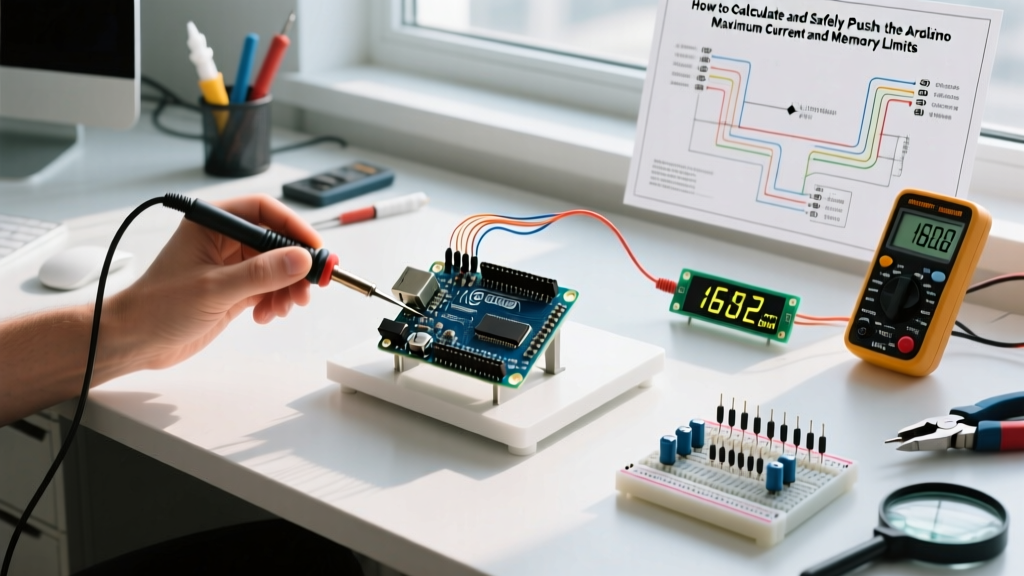

Understanding the Arduino Maximum Hardware Limits
When designing complex embedded systems, robotics, or high-speed data loggers, you will eventually hit the physical boundaries of your microcontroller. Determining the arduino maximum thresholds for your specific board is not just a theoretical exercise; it is a critical step in preventing silicon degradation, unexpected reboots, and catastrophic component failure. As of 2026, the maker ecosystem has largely transitioned from legacy 8-bit AVR chips to 32-bit ARM and Renesas architectures, meaning the historical rules of thumb no longer universally apply.
This comprehensive tutorial will guide you through calculating and safely testing the absolute limits of your board's GPIO current, SRAM/Flash memory, and serial baud rates. We will specifically contrast the legacy ATmega328P (Uno R3) with the modern Renesas RA4M1 (Uno R4 Minima) to highlight critical failure modes that catch many upgrading engineers off guard.
Step 1: Calculating the Arduino Maximum Pin Current
The most common way makers destroy their microcontrollers is by exceeding the maximum current sourcing or sinking capabilities of the GPIO pins. Every datasheet specifies two critical values: the Recommended Operating Condition and the Absolute Maximum Rating.
CRITICAL WARNING: The "Absolute Maximum" rating is the point at which permanent silicon damage begins. It is not a target operating point. Operating continuously at the absolute maximum accelerates electromigration inside the microscopic traces of the die, leading to premature failure. Always design your circuits around the recommended limits.
The Legacy vs. Modern Paradigm Shift
For over a decade, the community relied on the ATmega328P. However, if you have upgraded to the newer Uno R4 series, your current limits have drastically changed. Exceeding these limits on the R4 will instantly fry the I/O port.
| Board Model | Microcontroller | Max Pin Current (Recommended) | Absolute Max Pin Current | Total VCC/GND Limit |
|---|---|---|---|---|
| Uno R3 / Nano | ATmega328P (AVR) | 20 mA | 40 mA | 200 mA |
| Uno R4 Minima | Renesas RA4M1 (ARM Cortex-M4) | 8 mA | 15 mA | 80 mA |
| Mega 2560 | ATmega2560 (AVR) | 20 mA | 40 mA | 200 mA |
| Nano 33 IoT | SAMD21 (ARM Cortex-M0+) | 7 mA | 15 mA | ~50 mA |
Notice the severe drop in the arduino maximum pin current on the Uno R4 Minima. If you connect a standard 5V relay module that draws 15mA directly to an R4 GPIO pin, you are exceeding the absolute maximum rating. You must use a logic-level MOSFET (like the IRLZ44N) or a dedicated driver IC (like the ULN2003) for any load exceeding 8mA on modern 32-bit boards.
Step 2: Managing the Arduino Maximum Flash and SRAM Limits
Memory exhaustion is a silent killer of embedded projects. When your sketch exceeds the maximum SRAM, the stack and heap collide, resulting in random reboots or corrupted sensor data. To understand your constraints, consult the official Arduino Memory Guide for deep-dive architectures.
How to Check Memory Usage in the Arduino IDE
After compiling your sketch in Arduino IDE 2.x, the output console displays a memory estimation. However, this only accounts for static allocation (global variables and constants). It does not account for dynamic allocation (Strings, arrays created inside loops) or the stack depth required by recursive functions or heavy library calls like the SD or WiFi libraries.
To find the true available SRAM at runtime, use this memory-checking function:
int freeRam() {
  extern int __heap_start, *__brkval;
  int v;
  return (int) &v - (__brkval == 0 ? (int) &__heap_start : (int) __brkval);
}
Pushing the Limits with the F() Macro and PROGMEM
String literals in your code (e.g., Serial.println("Hello World");) are copied from Flash memory into SRAM at boot. On an Uno R3 with only 2KB of SRAM, a few dozen debug strings will max out your memory. To bypass this and push your SRAM to its maximum usable limit, wrap your literals in the F() macro:
Serial.println(F("This string stays in Flash and saves SRAM"));For large lookup tables, sensor calibration arrays, or bitmap images, store them in Flash using the PROGMEM attribute. This allows you to utilize the full 32KB (or 256KB on the Mega/R4) of Flash memory without touching the volatile SRAM.
Step 3: Pushing the Arduino Maximum Serial Baud Rate
The standard serial baud rate is 9600 or 115200 bps. However, when streaming high-frequency sensor data (like 9-axis IMU readings at 1kHz), you will hit the serial bottleneck. The arduino maximum reliable baud rate is dictated by the microcontroller's clock speed and the UART hardware divider.
- 16 MHz AVR Boards (Uno R3, Mega): The theoretical maximum is 2,000,000 bps (2 Mbps). However, due to integer division errors in the baud rate generator, rates above 500,000 bps suffer from high bit-error rates (BER). The highest reliable rate with less than 2% error is 250,000 bps or 500,000 bps.
- 48 MHz ARM/Renesas Boards (Uno R4, Nano 33): These boards feature fractional baud rate generators. You can reliably push the serial connection to 1,000,000 bps (1 Mbps) or even 2,000,000 bps with near-zero error margins, provided your USB-to-Serial bridge chip (like the CH340 or native USB controller) and your receiving PC's UART adapter can handle the throughput.
Pro-Tip: If you require data rates beyond 2 Mbps, abandon hardware UART over USB and switch to SPI or I2C communication to a dedicated high-speed FTDI or CP2102N bridge, or utilize the native USB HID/CDC endpoints available on boards like the Leonardo or Uno R4.
Step 4: Real-World Testing with a Multimeter
Do not trust software estimations for power draw. To verify you are operating within the arduino maximum current limits, perform a physical shunt test.
- Prepare the Shunt: Cut the 5V trace on your custom PCB, or if using a dev board, power the Arduino via the 5V pin from an external benchtop power supply.
- Insert the Multimeter: Set your digital multimeter (DMM) to the 10A or mA current setting. Place the DMM in series between your power supply's positive terminal and the Arduino's 5V input.
- Establish a Baseline: Upload a blank sketch. A standard Uno R3 draws roughly 45mA at idle. An Uno R4 Minima draws roughly 25mA.
- Actuate Loads: Trigger your relays, LEDs, and motors one by one. Observe the current spikes. Ensure the total aggregate current never exceeds the board's main voltage regulator limit (typically 800mA to 1A for the onboard linear regulators, though they will overheat and thermal-throttle long before reaching 1A without a heatsink).
- Measure Pin-Specific Draw: To test a specific GPIO pin, wire the load to the pin, and place the multimeter in series between the GPIO pin and the load. Verify the reading stays below the recommended limits outlined in the table above.
Frequently Asked Questions
What happens if I exceed the absolute maximum current on a single pin?
In the best-case scenario, the internal protection diodes will overheat, and the pin will become "stuck" HIGH or LOW, effectively dying while the rest of the microcontroller survives. In the worst-case scenario, the excessive current will melt the internal bond wires or trace routing inside the silicon die, causing a short circuit that destroys the entire MCU and potentially back-feeds 5V into your computer's USB port, damaging your motherboard.
Can I increase the Arduino maximum PWM frequency?
Yes. The default PWM frequency on pins 5 and 6 (Uno R3) is ~980 Hz, while pins 9, 10, and 11 operate at ~490 Hz. By directly manipulating the Timer/Counter Control Registers (TCCRnB) in the ATmega328P, you can push the PWM frequency up to 62.5 kHz. Be aware that increasing the frequency reduces the available duty-cycle resolution and can cause EMI (Electromagnetic Interference) issues with nearby audio or RF components.
Is there a maximum limit to the number of I2C devices I can connect?
The I2C protocol uses 7-bit addressing, allowing for 128 theoretical addresses (112 usable after reserved addresses). However, the physical arduino maximum is limited by bus capacitance. The I2C specification limits total bus capacitance to 400 pF. Every device, wire, and breadboard contact adds capacitance. In practice, without an I2C bus extender (like the PCA9615) or active pull-up resistors, you will experience data corruption if you connect more than 5 to 8 standard sensor modules on a single bus running at 400 kHz.
For more detailed hardware schematics and pinout diagrams to aid in your current calculations, always refer to the Arduino Uno R4 Minima Documentation or the specific Microchip ATmega328P Datasheet for legacy designs. Respecting these hardware boundaries is the hallmark of a professional embedded systems engineer.