
The Illusion of Simplicity in Robotics
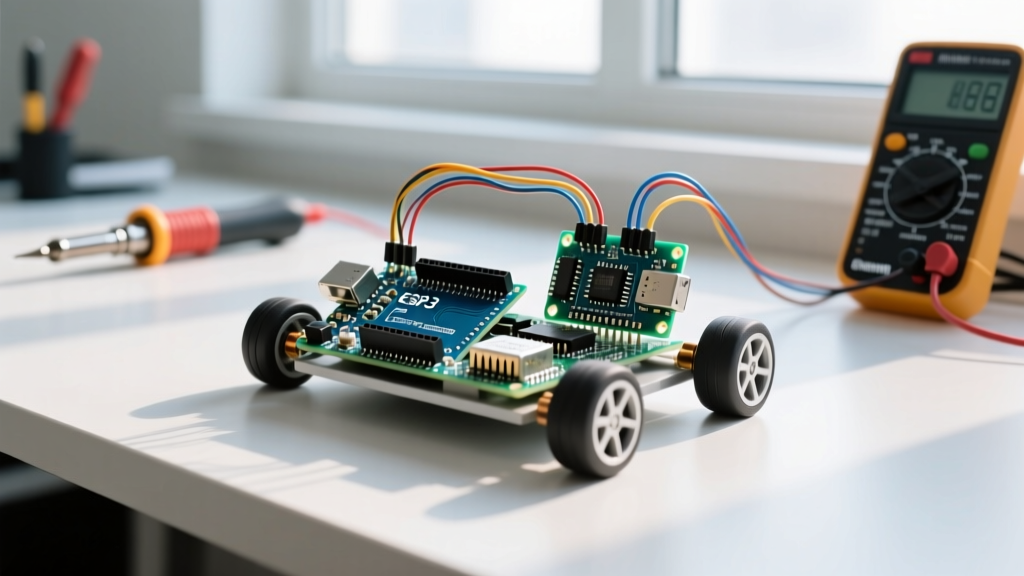
Building an Arduino controlled car is widely considered a rite of passage in the maker community. However, beneath the surface of a simple two-wheel-drive chassis lies a complex intersection of embedded systems, power electronics, and kinematic physics. While a basic sketch can make the wheels spin, transforming a rudimentary RC platform into a reliable, autonomous, or high-performance robotic vehicle requires a deep understanding of electromechanical integration. This guide deconstructs the core architecture of an Arduino controlled car, moving beyond basic wiring diagrams to explore the actual physics, component limitations, and power dynamics that dictate real-world performance.
The Microcontroller Boundary: Why GPIO Pins Fail
The most common point of failure for beginners is attempting to drive motors directly from the microcontroller. Modern boards like the Arduino Uno R4 Minima (priced around $17.50 in 2026) utilize the Renesas RA4M1 ARM Cortex-M4 processor, while the classic Uno R3 relies on the ATmega328P. Despite their processing capabilities, the General Purpose Input/Output (GPIO) pins on these boards are strictly limited to sourcing or sinking approximately 20mA to 40mA per pin.
A standard TT gearmotor (the ubiquitous yellow plastic motors found in most starter kits) draws roughly 200mA at no-load and can spike to 2A or more during a stall condition. If you attempt to pull 2A through a 40mA-rated GPIO pin, you will instantly vaporize the internal silicon traces, permanently destroying the microcontroller. Therefore, an intermediary power stage is mandatory to isolate the low-voltage logic circuit from the high-current motor circuit.
H-Bridge Topology and Motor Driver Selection
To control both the speed and direction of a DC motor, we use an H-Bridge. This circuit consists of four electronic switches (typically MOSFETs or BJTs) arranged in an 'H' pattern. By closing specific pairs of switches, current can be routed through the motor in either direction, while Pulse Width Modulation (PWM) applied to the enable pins dictates the speed.
Selecting the right motor driver is critical for efficiency and thermal management. Below is a comparison of the three most prevalent motor driver ICs used in Arduino controlled car builds today:
| IC Model | Switch Topology | Peak Current | Voltage Drop | Typical 2026 Price |
|---|---|---|---|---|
| L298N | BJT Darlington | 2.0A per channel | ~2.0V | $3.50 - $5.00 |
| TB6612FNG | MOSFET | 1.2A per channel | ~0.5V | $5.00 - $7.00 |
| DRV8871 | MOSFET | 3.6A per channel | ~0.2V | $4.50 - $6.00 |
The L298N is a legacy bipolar junction transistor (BJT) design. Its primary flaw is the massive 2.0V voltage drop across the Darlington pairs. If you supply 6V to the driver, your motor only receives 4V, with the remaining energy wasted as heat. Modern designs heavily favor MOSFET-based drivers like the TB6612FNG or Texas Instruments' DRV8871 portfolio, which offer significantly lower on-resistance (Rds-on), resulting in minimal voltage drop and vastly superior battery life.
Power Architecture: Chemistry, Internal Resistance, and Sag
An Arduino controlled car requires two distinct power domains: the logic rail (5V or 3.3V) and the motor rail (6V to 12V). Sharing a single power source without proper regulation leads to brownouts. When a motor accelerates or hits a physical obstacle, it draws a massive inrush current. This causes the battery voltage to temporarily sag due to the battery's Internal Resistance (IR).
Battery Chemistry and Voltage Sag
Using standard AA alkaline batteries is a frequent mistake. Alkaline cells have a high internal resistance (often exceeding 0.15 ohms per cell). A 4-cell AA pack (6V nominal) experiencing a 2A stall current will sag by over 1.2V, dropping the voltage below the threshold required to keep the Arduino's onboard voltage regulator stable, causing the microcontroller to reset mid-drive.
Instead, professional builds utilize Lithium-ion chemistries. A 2S LiPo (7.4V nominal, 8.4V fully charged) or a pair of high-discharge 18650 cells (like the Samsung 25R, capable of 20A continuous discharge) possess an internal resistance of roughly 0.02 ohms. This ensures the voltage remains rock-solid even under heavy kinetic loads.
The Flyback Diode and Back-EMF
DC motors are inductive loads. When the H-Bridge switches off, the collapsing magnetic field inside the motor coils generates a reverse voltage spike known as Back-Electromotive Force (Back-EMF). Without flyback diodes to safely recirculate this current, the voltage spike can exceed 50V, instantly piercing the gate oxide of your MOSFETs. While modern ICs like the DRV8871 integrate these diodes on-chip, older discrete H-bridge builds require external Schottky diodes (such as the 1N5819) wired in reverse bias across the motor terminals.
PWM Dynamics and Acoustic Resonance
Speed control in an Arduino controlled car is achieved via Pulse Width Modulation. The microcontroller rapidly toggles the power pin on and off. A 50% duty cycle effectively delivers half the battery voltage to the motor. However, the frequency of this toggling matters immensely.
According to the official Arduino analogWrite() documentation, most PWM pins on the Uno operate at a default frequency of 490Hz. Pins 5 and 6 operate at 980Hz. When a 490Hz PWM signal is applied to a DC motor, the rapid physical engagement and disengagement of the rotor can cause the motor casing to vibrate at an audible frequency, resulting in an annoying high-pitched whine. By manipulating the hardware timers (Timer0, Timer1, Timer2) via direct register manipulation, advanced builders can push the PWM frequency above 20kHz, moving the switching noise entirely out of the range of human hearing and resulting in a silent, smooth drive.
Differential Drive Kinematics and the PWM Deadzone
Most Arduino cars utilize a differential drive (skid-steer) configuration. There is no steering rack; instead, turning is achieved by driving the left and right wheels at different speeds or in opposite directions. The kinematic equations for a skid-steer rover dictate that the turning radius is a function of the track width (distance between wheels) and the velocity delta between the two sides.
The PWM Deadzone Phenomenon: A critical concept in motor control is the 'deadzone.' Due to static friction and the mechanical binding of the gearbox, a TT gearmotor will not begin to spin until a minimum threshold of voltage is applied. On a standard 6V system, sending a PWM value of 10 (out of 255) will result in zero movement. The motor typically requires a PWM value of at least 70 to 90 (roughly 30-35% duty cycle) to break static inertia. Software architectures must account for this deadzone by mapping joystick inputs non-linearly, ensuring that the moment the car breaks traction, it does not violently lurch forward.
For precision applications, builders upgrade from cheap TT motors to N20 micro metal gearmotors. As detailed in Pololu's comprehensive guide to brushed DC gearmotors, selecting the correct gear ratio (e.g., 1:100 for high torque vs 1:30 for high speed) fundamentally alters the current draw and the required PWM deadzone compensation.
Closing the Loop: Sensor Fusion for Autonomy
An open-loop Arduino controlled car simply executes blind commands. To achieve true autonomy, the system must transition to closed-loop control using sensor fusion. While the HC-SR04 ultrasonic sensor is the traditional choice for obstacle avoidance (costing under $2), it suffers from acoustic blind spots and struggles with sound-absorbing materials like fabric or foam.
Modern 2026 builds increasingly rely on Time-of-Flight (ToF) optical sensors like the VL53L1X or VL53L3CX. These I2C-based laser rangefinders provide millimeter-accurate distance readings up to 400cm, completely immune to acoustic interference. Furthermore, adding magnetic quadrature encoders to the rear shafts of the motors allows the Arduino to measure exact wheel RPM. By implementing a PID (Proportional-Integral-Derivative) control loop, the microcontroller can constantly adjust the PWM duty cycle to ensure both wheels are spinning at the exact same RPM, forcing the car to drive in a perfectly straight line even on uneven terrain.
Summary
Designing a high-performance Arduino controlled car requires looking past the basic code examples. By selecting efficient MOSFET-based motor drivers, utilizing low-resistance lithium power architectures, compensating for PWM deadzones, and integrating closed-loop sensor feedback, you elevate a simple toy into a robust, highly capable robotic platform.