
The Hidden Cost of the Arduino Delay Function
Every maker's journey begins with the same line of code: delay(1000);. It is the undisputed king of introductory sketches, offering a trivial way to blink an LED or pace a serial output. However, as projects evolve from simple test circuits into complex 2026 IoT nodes featuring OLED displays, environmental sensors, and wireless telemetry, the arduino delay function transitions from a helpful tool into a critical architectural bottleneck.
At the hardware level, the Arduino delay() Reference halts the main execution thread. On classic 16MHz ATmega328P boards, this is implemented as a busy-wait loop that counts timer overflows. On modern 32-bit architectures like the Renesas RA4M1 (found in the Arduino Uno R4 Minima) or the dual-core ESP32-S3, the underlying implementation may yield to background RTOS tasks, but it still entirely blocks your user-space application logic.
This blocking behavior introduces severe failure modes in advanced circuits:
- Missed Interrupts & Edge Cases: While interrupts still fire during a delay, if your logic relies on polling (like reading a mechanical rotary encoder or a capacitive touch pin), a 500ms delay guarantees you will miss rapid state changes.
- I2C Bus Lockups: When communicating with sensors like the BME280 or displays like the SSD1306, the Wire library requires precise timing. Inserting blocking delays between I2C transactions can allow bus capacitance to drift or cause slave devices to timeout, resulting in NACK errors and frozen sketches.
- Watchdog Timer (WDT) Resets: On WiFi-enabled boards like the ESP32-S3 or Raspberry Pi Pico 2 (RP2350), the network stack requires constant CPU cycles. A blocking delay of more than a few seconds in the
loop()can starve the WiFi task, triggering the Task Watchdog Timer (TWDT) and causing a continuous reboot loop.
Migration Phase 1: The millis() State Machine
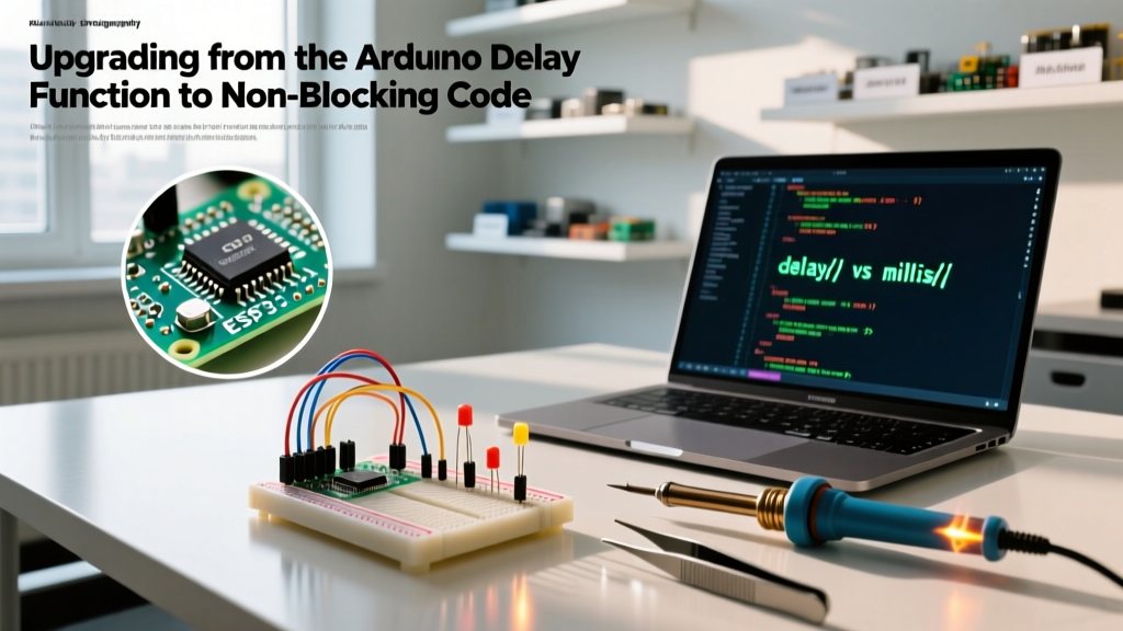
The first step in upgrading your firmware is replacing time-based blocking with event-driven polling using millis(). This function returns the number of milliseconds since the board began running the current program. By recording timestamps and comparing them, you can execute code at precise intervals without stopping the CPU.
Solving the 49.7-Day Rollover Bug
The most common mistake makers make when migrating away from the arduino delay function is writing flawed comparison logic. The millis() counter is stored as an unsigned long (32 bits), which maxes out at 4,294,967,295 milliseconds (approximately 49.7 days) before rolling over to zero.
If you use absolute time comparisons (e.g., if (currentMillis > previousMillis + interval)), your code will catastrophically fail at the 49.7-day mark. The mathematically robust solution relies on unsigned integer underflow properties, as documented in the Arduino millis() Reference.
unsigned long previousMillis = 0;
const long interval = 1000;

void loop() {
  unsigned long currentMillis = millis();

  // The correct, rollover-safe subtraction method
  if (currentMillis - previousMillis >= interval) {
    previousMillis = currentMillis;

    // Non-blocking action goes here
    toggleLED();
  }

  // The CPU is free to handle other tasks immediately
  readButtons();
  updateDisplay();
}
Pro Tip: Never useintorsigned longfor timing variables. Always useunsigned longto ensure the bitwise wrap-around mathematics function correctly during the 49.7-day rollover event.
Migration Phase 2: Hardware Timers for Microsecond Precision
While millis() is excellent for human-scale interactions (UI updates, sensor polling), it lacks the precision required for signal generation. The resolution of millis() is limited by the system tick rate, and execution jitter can introduce timing errors of 1-4 milliseconds. If you are generating a 38kHz carrier wave for an IR transmitter or driving a high-speed stepper motor, you must migrate to hardware timers.
AVR vs. ARM Timer Architectures
On legacy AVR boards (Uno, Nano, Mega), you can utilize the TimerOne library to attach an interrupt service routine (ISR) to the 16-bit Timer1 peripheral. This allows you to trigger a function exactly every 10 microseconds without consuming any main-loop CPU cycles.
On modern ARM Cortex-M0+ and Cortex-M4 boards like the Raspberry Pi Pico 2 (RP2350), the paradigm shifts. The RP2350 features dedicated Programmable I/O (PIO) state machines. Instead of relying on CPU timers, you can offload precise timing and signal generation entirely to the PIO blocks, freeing both main CPU cores for complex application logic while the hardware handles the microsecond-level delays autonomously.
Migration Phase 3: Upgrading to RTOS Task Management
For complex, multi-threaded IoT applications running on the ESP32-S3, ESP32-C6, or RP2350, the ultimate upgrade is abandoning the traditional Arduino setup() and loop() paradigm in favor of a Real-Time Operating System (RTOS) like FreeRTOS.
In an RTOS environment, blocking delays are replaced by task-yielding delays. When you call the FreeRTOS vTaskDelay Documentation equivalent, the CPU does not sit idle. Instead, the scheduler pauses your specific task and instantly allocates the CPU cycles to other tasks (like maintaining a TLS-encrypted MQTT connection or scanning for BLE beacons).
#include <Arduino_FreeRTOS.h>

void sensorTask(void *pvParameters) {
  for (;;) {
    readBME280Sensor();
    // Yields CPU to other tasks for exactly 2000ms
    vTaskDelay(pdMS_TO_TICKS(2000));
  }
}

void wifiTask(void *pvParameters) {
  for (;;) {
    maintainMQTTConnection();
    // Short yield to prevent Watchdog resets
    vTaskDelay(pdMS_TO_TICKS(10));
  }
}
By compartmentalizing your firmware into discrete RTOS tasks, you eliminate the need for complex millis() state machines. Each task operates as if it has its own dedicated microcontroller, complete with its own non-blocking delay mechanisms.
Timing Method Comparison Matrix
Selecting the correct timing architecture depends on your specific hardware constraints and precision requirements. Use the following matrix to guide your migration strategy:
| Timing Method | CPU State | Precision | RAM Overhead | Ideal 2026 Use Case |
|---|---|---|---|---|
| delay() | Blocking (Busy-wait) | Low (ms) | 0 bytes | Initial hardware bring-up, simple setup routines |
| millis() | Non-blocking (Polling) | Medium (1-4ms) | 4 bytes per timer | Debouncing buttons, fading LEDs, polling I2C sensors |
| Hardware Timers | Non-blocking (ISR) | High (ns-µs) | ~20 bytes | IR carrier generation, PID control loops, encoders |
| RTOS vTaskDelay | Yielding (OS Managed) | High (Tick rate) | ~256+ bytes per task | Concurrent WiFi/BLE stacks, audio processing, complex UI |
Real-World Edge Cases and Troubleshooting
The I2C Timeout Trap
A frequent failure mode occurs when makers use the arduino delay function to 'wait' for an I2C sensor to finish a high-resolution measurement. For example, the TSL2591 light sensor requires up to 600ms for a maximum-gain integration. If you use delay(600), and the I2C SDA line experiences a noise spike, the Wire library may hang indefinitely waiting for a clock stretch that never resolves. By migrating to a millis() based state machine, you can implement a software timeout that resets the I2C bus via bit-banging if the sensor fails to respond within the expected window.
ADC Settling Times
When reading high-impedance analog sensors (like a voltage divider monitoring a LiPo battery), the internal sample-and-hold capacitor of the microcontroller's ADC requires time to charge. Beginners often insert a delay(10) between analog reads. A superior, non-blocking approach is to trigger the ADC conversion via an interrupt, allowing the CPU to execute thousands of instructions while the hardware peripheral silently gathers the analog data.
Conclusion
Migrating away from the arduino delay function is the defining threshold between a hobbyist tinkerer and an embedded systems engineer. By mastering millis() rollover mathematics, leveraging hardware-specific timers, and adopting RTOS task scheduling on modern 32-bit microcontrollers, you unlock the full computational potential of your hardware. Your sketches will become responsive, resilient to network latency, and capable of handling the demanding multi-sensor environments of modern maker projects.