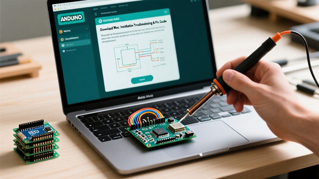

Why Build a Custom Arduino USB Wire?
When integrating a microcontroller into a custom 3D-printed, aluminum, or acrylic enclosure, relying on a standard off-the-shelf cable protruding from the board's edge is rarely an option. A custom Arduino USB wire setup—specifically a panel-mount extension or pigtail—allows you to route the connection cleanly to the exterior of your project box while maintaining reliable data transfer and power delivery. Whether you are building a custom MIDI controller, an industrial sensor node, or a permanent IoT gateway, extending the USB interface requires an understanding of signal integrity, wire gauge selection, and precise soldering techniques.
In this comprehensive tutorial, we will walk through the exact process of designing, stripping, soldering, and shielding a custom Arduino USB wire harness. We will focus on USB 2.0 Full-Speed (12 Mbps) requirements, which govern the vast majority of Arduino boards utilizing the ATmega16U2 or CH340 serial-to-USB bridge chips.
Component Selection & 2026 Material Costs
The reliability of your custom harness depends entirely on material quality. Skipping shielded wire or using undersized power conductors will result in voltage drops and enumeration failures. Below is the recommended bill of materials (BOM) for a professional-grade panel-mount USB wire build.
- Panel-Mount Connector: Molex or Amphenol USB 2.0 Type-B or Micro-B panel-mount receptacle. These typically feature a standard 16mm or 22mm cutout requirement and include a dust cap. (Cost: $4.50 - $8.00)
- Data Wire (D+ / D-): 28 AWG stranded, shielded twisted pair. Alpha Wire or Belden spec wire is ideal to maintain the required 90-ohm differential impedance. (Cost: $12.00 per 10ft spool)
- Power Wire (VBUS / GND): 22 AWG or 20 AWG stranded silicone wire to minimize voltage drop over runs longer than 12 inches. (Cost: $8.00 per spool)
- Soldering Station: A temperature-controlled station like the Weller WE1010NA or Hakko FX-888D (approx. $115 - $130 in 2026) is mandatory for consistent thermal recovery on ground planes.
- Consumables: Kester 63/37 Sn/Pb rosin-core solder (0.031" diameter), Chip Quik NC191 gel flux, and 3M copper foil shielding tape.
USB 2.0 Pinout & Signal Requirements
Before applying heat, you must understand the pinout. The Arduino Uno R3 and Mega 2560 utilize a USB Type-B connector, while the Nano and Pro Micro use Micro-USB or Mini-USB. The internal electrical mapping for USB 2.0 remains consistent across these physical form factors.
| Pin Number | Signal Name | Wire Color (Standard) | Function & Specification |
|---|---|---|---|
| 1 | VBUS | Red | +5V DC Power (Max 500mA draw for bus-powered) |
| 2 | D- | White | Data Minus (Differential Pair, 90Ω impedance) |
| 3 | D+ | Green | Data Plus (Differential Pair, 90Ω impedance) |
| 4 | GND | Black | Signal and Power Ground Return |
| Shell | Shield | Bare/Drain | EMI Shielding (Connect to chassis/ground at one end) |
For authoritative hardware layout guidelines, refer to the USB Implementers Forum (USB-IF) developer documentation, which outlines strict capacitance and impedance limits for Full-Speed devices.
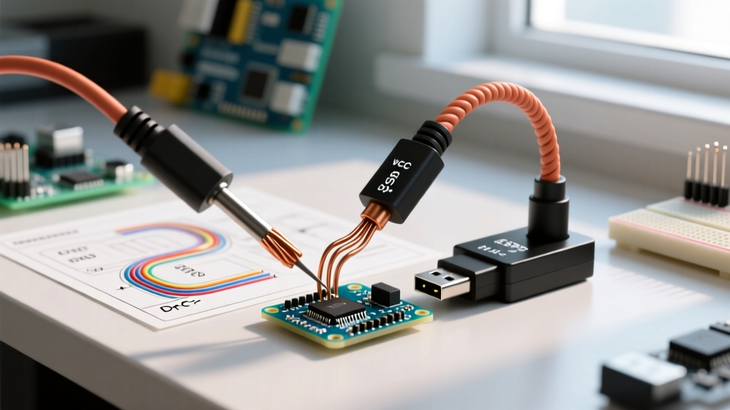
Step-by-Step Soldering & Assembly Guide
Creating a custom Arduino USB wire requires a disciplined sequence to avoid cold joints and thermal damage to the panel-mount connector's plastic housing.
Step 1: Cable Preparation and Stripping
Cut your 28 AWG data wires to the exact length needed plus 1 inch of slack. Strip exactly 3mm of insulation from the data wires and 5mm from the 22 AWG power wires. Pro Tip: Use a precision thermal wire stripper (like the Hakko CHP HSD-10) to avoid nicking the copper strands, which increases resistance and creates weak points.
Step 2: Tinning the Conductors
Set your soldering iron to 320°C (if using lead-free) or 300°C (for 63/37 Sn/Pb). Apply a microscopic amount of flux to the stripped ends. Touch the iron to the wire and feed solder until the strands wick the solder uniformly. The tinned length should not exceed 2.5mm to prevent the wire from becoming too rigid and shorting against adjacent pins.
Step 3: Soldering the Panel-Mount Receptacle
Secure the Molex USB panel-mount connector in a helping-hands vise. Solder in the following order to manage heat distribution:
- GND (Pin 4): Solder the black 22 AWG wire. The ground pin often has a larger thermal mass connected to the shell.
- VBUS (Pin 1): Solder the red 22 AWG wire.
- D- (Pin 2) & D+ (Pin 3): Solder the 28 AWG white and green wires. Use minimal solder and remove the iron immediately to prevent melting the internal plastic core of the receptacle.
Step 4: Shielding and Strain Relief
Once the connections are verified with a multimeter for continuity and absence of shorts, wrap the soldered pins in Kapton tape for electrical isolation. Next, wrap the exposed wire bundle in 3M copper foil tape, ensuring the tape makes contact with the connector's metal shell and the drain wire. Finish by sliding a piece of adhesive-lined heat shrink tubing over the entire joint and applying heat until the internal adhesive seals the cable entry point.
Expert Insight: Never leave the data lines unshielded for more than 15mm. USB 2.0 Full-Speed signaling is highly susceptible to electromagnetic interference (EMI) from nearby stepper motor drivers or switching power supplies commonly found in maker projects.
Signal Integrity: Managing Impedance and Routing
The most common mistake makers make when building an Arduino USB wire is treating the data lines like standard DC power wires. The D+ and D- lines carry high-frequency differential signals. If the wires are routed parallel to noisy AC lines or if the twisted pair is untwisted too far back from the solder joint, signal reflections will occur.
To maintain the 90-ohm differential impedance required by the USB 2.0 specification:
- Keep the untwisted "pigtail" length of the D+ and D- wires under 10mm at both the panel mount and the Arduino header.
- Avoid routing the USB harness directly over the Arduino's onboard switching regulator (the 5V or 3.3V buck converter), as the high-frequency switching noise can couple into the data lines.
- If your enclosure is metal, tie the USB shell shield to the chassis ground at the panel mount point only, leaving the Arduino-side shield floating to prevent ground loops.
Troubleshooting Common USB Enumeration Failures
Even with meticulous soldering, custom wiring can introduce faults. If your PC fails to recognize the Arduino, or if the Arduino IDE fails to upload sketches, consult the diagnostic matrix below.
| Symptom / Error Message | Probable Cause in Custom Wiring | Diagnostic & Fix |
|---|---|---|
| "USB Device Not Recognized" (Windows) | D+ / D- crosstalk or broken differential pair. | Check continuity on Pins 2 & 3. Ensure data wires are not crushed or untwisted. Re-solder with shorter pigtails. |
| "Power Surge on Hub Port" | VBUS shorted to GND, or shield wire shorting to D-. | Use a multimeter in resistance mode. VBUS to GND should read open (OL) when unplugged. Check for stray solder bridges. |
| Arduino connects, but drops during sketch upload | Voltage drop on VBUS due to undersized wire or excessive length. | Measure voltage at the Arduino's 5V pin while uploading. If it drops below 4.6V, upgrade VBUS/GND to 18 AWG wire. |
| Intermittent COM Port disconnects | Poor strain relief causing micro-fractures in solder joints. | Apply hot glue or adhesive-lined heat shrink at the connector exit to absorb mechanical flexing. |
Final Verification and Testing
Before sealing your enclosure, perform a "burn-in" test. Plug the custom Arduino USB wire into a powered USB 2.0 hub and upload a stress-test sketch that rapidly toggles the onboard LED and sends serial data back to the PC at 115200 baud. Let it run for 30 minutes. If the COM port remains stable and the serial monitor shows no corrupted characters, your impedance matching and shielding are adequate.
Building a custom Arduino USB wire takes roughly 45 minutes and costs less than $15 in raw materials, but it elevates a breadboard prototype into a robust, deployment-ready instrument. By respecting USB signal integrity rules and utilizing proper strain relief, your custom harness will outlast commercial off-the-shelf cables in demanding environments.