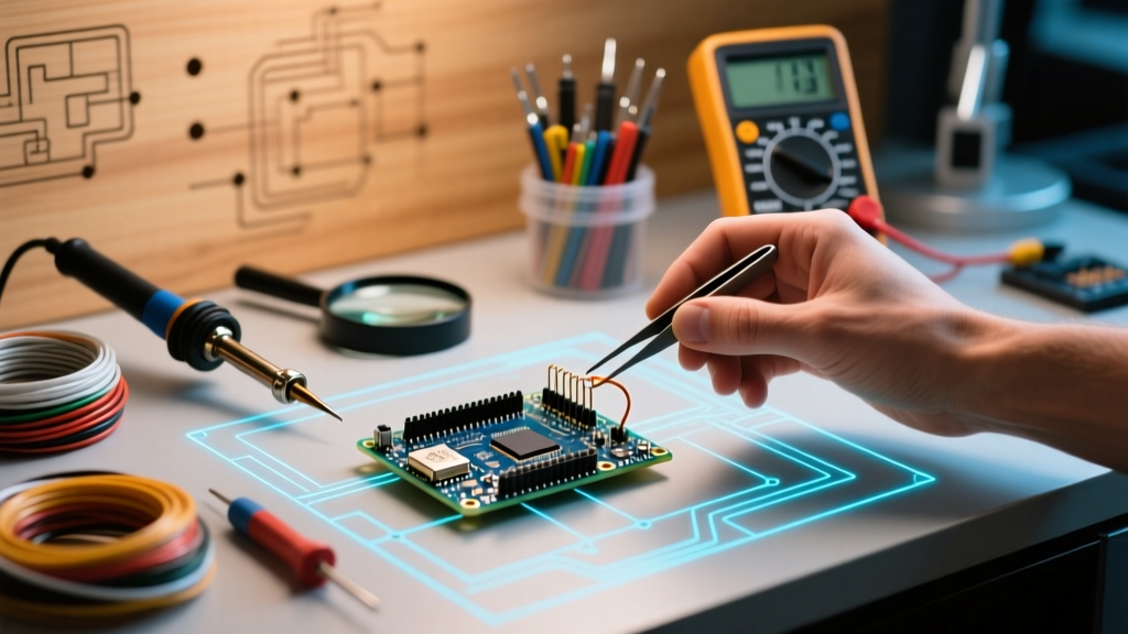
The Hidden Tax of the Prototyping Rat's Nest
When building microcontroller circuits, the physical layer is often the most neglected. Makers spend hours optimizing C++ code or selecting the perfect sensor, only to have their project fail due to a loose, oxidized, or undersized wire. Optimizing your jumper cables Arduino workflow is not merely an exercise in bench aesthetics; it is a critical engineering practice that directly impacts signal integrity, power delivery, and debugging speed.
A disorganized breadboard with mismatched wires creates a 'rat's nest' that obscures routing errors and makes intermittent faults nearly impossible to trace. By treating your interconnects as a formalized system rather than an afterthought, you can reduce hardware debugging time by up to 40%. This guide details how to select, organize, and route your jumper wires to establish a professional-grade prototyping workflow.
Stamped vs. Turned Pins: The Contact Resistance Trap
The vast majority of budget jumper wire kits utilize standard 2.54mm pitch Dupont-style connectors. However, not all Dupont connectors are manufactured equally. The internal metal contacts generally fall into two categories:
- Stamped (Folded) Contacts: Made by stamping and folding a flat sheet of brass or phosphor bronze. These are cheap to produce but offer limited surface area contact. Over time, the folded metal fatigues, leading to high contact resistance (often exceeding 50mΩ) and intermittent connections when the wire is bumped.
- Turned (Machined) Contacts: CNC-machined from a solid cylinder of brass and usually gold or tin-plated. These provide 360-degree radial contact with the header pin. While they cost roughly 30% more, their contact resistance remains consistently below 10mΩ, making them essential for precision analog readings and high-current paths.
Workflow Tip: Keep a dedicated pair of flush cutters and a small flathead screwdriver on your bench. If a stamped connector feels 'loose' on an Arduino header pin, use the screwdriver to gently pry the plastic tab and remove the wire. Do not attempt to squeeze the metal contact with pliers, as this work-hardens the brass and guarantees future failure.
Strategic Gauge Selection: The 28 AWG vs. 24 AWG Debate
Standard pre-crimped jumper wires are almost universally 28 AWG (approx. 0.32mm² cross-section). While perfectly adequate for low-current logic signals like I2C or UART, 28 AWG is a severe bottleneck for power distribution. According to SparkFun's comprehensive wire guide, understanding American Wire Gauge (AWG) ratings is fundamental to preventing voltage drops.
Consider a common scenario: powering a high-torque MG996R servo or a strip of 30 WS2812B NeoPixels from your Arduino's 5V rail. These loads can easily draw 1.5A to 2A in peak bursts. Copper wire at 28 AWG has a resistance of roughly 213 Ω/km. If you use a 30cm jumper wire to deliver power, the total loop (VCC and GND) is 60cm. At 2A, Ohm's Law (V = IR) dictates a voltage drop of roughly 0.25V. For a servo expecting a clean 5.0V, receiving 4.75V under load can trigger brownout resets in your microcontroller's voltage regulator.
The 2026 Material Standard: Silicone over PVC
Historically, jumper wires were insulated with rigid PVC. Today, premium workflow optimization demands silicone-jacketed wires. Silicone insulation offers two massive advantages:
- Thermal Resilience: Silicone withstands temperatures up to 200°C. If your soldering iron accidentally grazes a wire while working on an adjacent perfboard, PVC will melt and short, while silicone will simply shrug it off.
- Extreme Flexibility: Silicone wires use highly stranded copper (often 40+ strands for 24 AWG), allowing them to bend into tight radii without exerting mechanical stress on the breadboard contacts or Arduino headers.
Jumper Wire Selection Matrix
| Wire Type | Gauge | Jacket Material | Max Current | Best Use Case | Est. Cost (per 120pcs) |
|---|---|---|---|---|---|
| Standard Dupont | 28 AWG | PVC | 1.0A | Logic signals, I2C, UART, basic sensors | $4.00 - $7.00 |
| Premium Power | 24 AWG | Silicone | 3.5A | 5V/3.3V Rails, Servos, LED Strips, Motors | $14.00 - $19.00 |
| Ribbon Cable | 28 AWG | PVC | 1.0A | Parallel buses, LCD displays (low speed) | $6.00 - $9.00 |
| Test Leads (Banana) | 18 AWG | Silicone | 10A+ | Main power supply to breadboard distribution | $12.00 (per pair) |
Implementing a Strict DC Color-Code Protocol
Randomly grabbing wires from a bin is the enemy of efficient troubleshooting. Professional electrical engineering relies on standardized color codes. While AC mains wiring is governed by strict NEC/IEC codes, low-voltage DC prototyping often lacks enforcement. To optimize your workflow, adopt a rigid internal color standard based on modified IEC 60446 principles.
Print this legend and tape it to your bench or pegboard:
- Red: Primary VCC (5V or main unregulated input)
- Black: Ground (GND) - Never use any other color for ground.
- Orange: Secondary VCC (3.3V logic level)
- Yellow: I2C SDA (Data)
- Green: I2C SCL (Clock)
- Blue: SPI Bus lines (MOSI, MISO, SCK)
- Purple: Analog Inputs (ADC)
- White/Grey: Digital GPIO / Chip Select (CS)
By strictly enforcing this palette, a glance at your board immediately reveals if an analog sensor is mistakenly plugged into an I2C bus, or if a 5V rail is accidentally feeding a 3.3V logic pin.
Signal Integrity: Routing High-Speed Buses
As microcontrollers become faster, the physical routing of jumper cables begins to impact data transmission. When working with high-speed SPI peripherals (like SD card modules, TFT displays, or external flash memory), long, parallel jumper wires act as antennas and capacitors.
The Crosstalk Problem
If you route an SPI Clock (SCK) line parallel to a MISO line for 15cm using standard ribbon cable, the capacitive coupling between the wires can cause the clock edge to bleed into the data line. This results in corrupted data packets and frustrating 'SD card initialization failed' errors. As noted in Adafruit's breadboarding tutorials, understanding the physical limitations of temporary connections is vital for high-frequency circuits.
Optimization Techniques for SPI/I2C
- Minimize Length: Keep SPI and I2C jumper cables under 10cm (4 inches). If the sensor must be further away, it is time to abandon jumper wires and use a shielded twisted-pair cable or a custom PCB.
- Avoid Ribbon Cables for SPI: Never use flat ribbon cables for high-speed clock lines. The uniform parallel spacing maximizes crosstalk.
- Add Local Decoupling: When running power and data over jumper cables to a remote sensor, always solder a 100nF ceramic capacitor directly across the VCC and GND pins at the sensor end of the jumper wires to filter out inductive noise introduced by the wire length.
Advanced Troubleshooting: Beyond the 'Wiggle Test'
When a circuit fails, the amateur response is the 'wiggle test'—pushing on wires until the system temporarily works. This is a poor workflow that masks the root cause. Instead, implement systematic continuity mapping.
Invest in a high-quality Digital Multimeter (DMM) with a fast-responding continuity beeper (such as the Brymen BM235 or Fluke 117). When debugging a complex jumper setup:
- Power Down: Disconnect the Arduino from USB and external power.
- Map the Rails: Probe every 5th hole along your breadboard's power rails. Breadboard power rails often have physical breaks in the center (common on 830-point boards). A missing jumper bridging the center gap is a classic hidden fault.
- The Pull-Test: Gently pull on the wire near the crimp, not the middle of the cable. If the wire stretches or the plastic housing separates from the metal pin, the crimp has failed. Discard the wire immediately; do not attempt to push it back in.
Pro-Tip for Intermittent I2C Faults: If your I2C devices randomly drop off the bus, the issue is rarely the code. It is almost always a marginal ground connection. Use a dedicated 24 AWG black silicone wire to create a 'star ground' directly from the Arduino's GND pin to the GND pin of every I2C sensor, bypassing the breadboard's thin internal metal clips entirely.
Knowing When to Abandon Jumper Wires
Part of workflow optimization is recognizing the limits of your tools. Jumper cables are for prototyping, not production or high-vibration environments. If your project involves moving parts (robotics), high current (>3A), or high-speed differential signaling (USB, CAN bus), jumper wires will fail.
At this stage, transition your workflow to screw-terminal breakout boards, Zero Insertion Force (ZIF) test sockets, or order a rapid-turnaround 2-layer PCB from a fab house. For a comprehensive look at moving from breadboard to PCB, review the official Arduino hardware documentation to ensure your pinout mappings are correct before finalizing your design.
Conclusion
Treating your jumper cables Arduino setup as a disciplined engineering workflow transforms prototyping from a frustrating guessing game into a predictable, efficient process. By upgrading to turned-pin connectors, utilizing 24 AWG silicone for power, enforcing a strict color code, and respecting the physics of high-speed signal routing, you eliminate entire categories of hardware bugs before you even write a line of code. A clean, well-routed bench is the hallmark of a maker who values their time and the reliability of their creations.