
The Ultimate Arduino Thermostat Quick Reference
Building a custom Arduino thermostat is a rite of passage for makers tackling HVAC automation, incubator control, or sous-vide cooking. However, moving from a blinking LED to switching 120V/240V AC loads based on thermal feedback introduces severe edge cases: relay chatter, sensor noise, and inductive load arcing. This FAQ and quick-reference guide cuts through the fluff, providing exact component specifications, wiring topologies, and logic frameworks required for a reliable build in 2026.
Component Selection Matrix
Before wiring, match your components to your specific thermal control application. Using the wrong sensor or switch is the root cause of 90% of thermostat failures.
| Component Type | Best For | Specific Model Recommendation | Approx. Cost (2026) |
|---|---|---|---|
| Temperature Sensor | Liquids, outdoor, long cable runs | Maxim/Analog Devices DS18B20+ (Waterproof) | $4.00 - $6.00 |
| Temperature Sensor | Indoor ambient air, enclosures | Sensirion SHT31-D (I2C, high accuracy) | $6.00 - $9.00 |
| Switching (Low Cycle) | Space heaters, slow HVAC fans | Songle SRD-05VDC-SL-C (Mechanical Relay) | $1.50 - $3.00 |
| Switching (High Cycle) | Sous-vide, 3D printer enclosures, PID | Omron G3NA-210B (Solid State Relay) | $10.00 - $14.00 |
Sensor Wiring & Troubleshooting FAQs
Q: Why should I choose the DS18B20 over the DHT22 for a thermostat?
The DHT22 is an air-temperature and humidity sensor that struggles with rapid thermal changes and cannot be submerged. The DS18B20 digital thermometer uses the 1-Wire protocol, offers ±0.5°C accuracy from -10°C to +85°C, and is available in waterproof stainless-steel probes. For any Arduino thermostat controlling liquids, outdoor environments, or drafty spaces, the DS18B20 is the undisputed standard.
Q: My DS18B20 is reading exactly 85°C or -127°C. What is wrong?
These are not random errors; they are specific hardware flags:
- 85°C Reading: This is the default power-on reset value of the sensor's scratchpad. It means the sensor is receiving power, but the Arduino is reading the data bus before the 750ms analog-to-digital conversion is complete. Fix: Add a
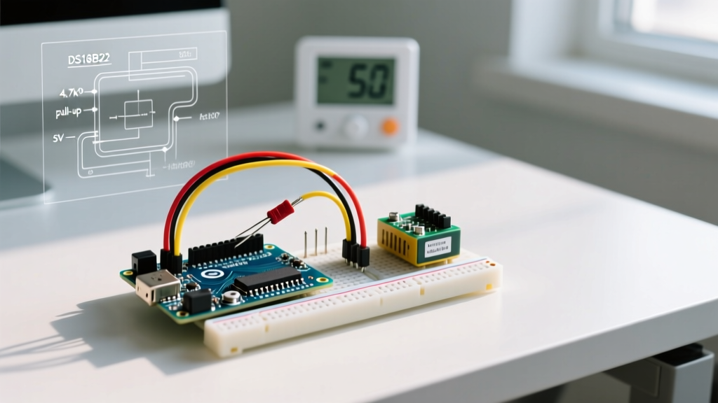
delay(750)after sending the convert temperature command, or use the non-blockingsetWaitForConversion(false)method in the DallasTemperature library. - -127°C Reading: The Arduino cannot see the sensor on the 1-Wire bus. This is almost always caused by a missing pull-up resistor or a parasitic power failure. Fix: Ensure a 4.7kΩ pull-up resistor is connected between the DATA line and VCC (3.3V or 5V).
Pro-Tip: Avoid Parasitic Power Mode
While the DS18B20 supports 'parasitic power' (drawing power directly from the data line), this mode limits current to roughly 1.5mA. If your waterproof probe cable exceeds 3 meters, the voltage drop will cause conversion failures. Always wire the sensor in external power mode (VDD to 5V, GND to GND, DATA to Pin) for reliable Arduino thermostat operation.
Relay Selection & Load Switching FAQs
Q: When must I use a Solid State Relay (SSR) instead of a mechanical relay?
Mechanical relays (like the common blue 5V modules) have physical contacts that degrade over time. If your thermostat uses simple 'Bang-Bang' control with a wide deadband, a mechanical relay will last for years. However, if you are implementing PID control (switching the load on and off multiple times per minute to maintain exact temperatures), mechanical contacts will arc, pit, and eventually weld shut within weeks. For high-cycle applications, use an SSR like the Omron G3NA-210B, which features zero-cross switching to minimize electromagnetic interference (EMI) and extends lifespan indefinitely.
Q: Do cheap optocoupler relay modules actually protect my Arduino?
Most generic 5V relay modules feature a PC817 optocoupler and a flyback diode. The flyback diode protects the switching transistor from the relay coil's inductive kickback. However, the optical isolation is often defeated on cheap boards because the VCC and JD-VCC jumper pins are bridged, sharing the same ground plane as the Arduino. To achieve true galvanic isolation and protect your microcontroller from AC mains transients, remove the jumper and power the relay coil side from a separate 5V isolated power supply.
Q: How do I prevent arcing when switching inductive HVAC loads?
If your Arduino thermostat is switching an AC compressor, fan motor, or transformer, the load is inductive. When the mechanical relay opens, the collapsing magnetic field generates a massive voltage spike that will arc across the contacts. You must install an RC Snubber circuit in parallel with the load. A standard snubber consists of a 100Ω carbon composition resistor in series with a 0.1μF X2-rated AC capacitor. For detailed relay safety topologies, consult the official Arduino relay wiring documentation.
Code Logic & Hysteresis FAQs
Q: What is hysteresis and why is my relay clicking rapidly?
Rapid clicking (chatter) occurs when the ambient temperature hovers exactly at your setpoint, causing the relay to toggle on and off every few seconds. This destroys mechanical relays and stresses HVAC compressors. You must implement hysteresis (a deadband) in your code.
Instead of a simple if (temp < setpoint) logic, use a state-based deadband approach:
- Heating Mode: Turn heater ON when
temp < (setpoint - deadband). - Heating Mode: Turn heater OFF when
temp >= setpoint.
A standard deadband for home HVAC is 1.0°C to 1.5°C. For precision incubators, reduce this to 0.2°C and switch to an SSR.
Q: Is PID control necessary for an Arduino thermostat?
Proportional-Integral-Derivative (PID) control is overkill for standard room heating but mandatory for applications requiring ±0.1°C stability, such as sous-vide water baths or reptile incubators. The OneWire and PID libraries available in the Arduino ecosystem make implementation straightforward. PID works by calculating the 'error' (difference between setpoint and current temp) and outputting a PWM signal to an SSR, effectively 'time-proportioning' the AC power to the heating element.
Rapid Troubleshooting Matrix
| Symptom | Probable Cause | Hardware / Code Fix |
|---|---|---|
| Relay clicks but load doesn't turn on | Insufficient coil current from Arduino 5V pin | Power relay module VCC via external 5V 1A USB supply; tie GNDs together. |
| Temperature readings fluctuate wildly | EMI from AC mains or switching transients | Route low-voltage sensor cables away from AC lines; add 100nF decoupling cap at sensor VCC. |
| Arduino resets when relay engages | Voltage sag on the 5V rail due to coil inrush | Upgrade Arduino power supply; ensure flyback diode is present on relay coil. |
| Heater stays ON permanently | Relay contacts welded shut from inductive arcing | Replace mechanical relay with SSR; install RC snubber across load. |
Final Safety Considerations
When integrating an Arduino thermostat into mains-powered environments, always enclose the high-voltage wiring in a grounded, fire-retardant junction box (such as ABS or Polycarbonate IP65 enclosures). Never rely solely on software limits; always wire a physical, bimetallic thermal fuse (e.g., a 10A 120°C cutoff) in series with your heating element as a catastrophic fail-safe against microcontroller lockups.