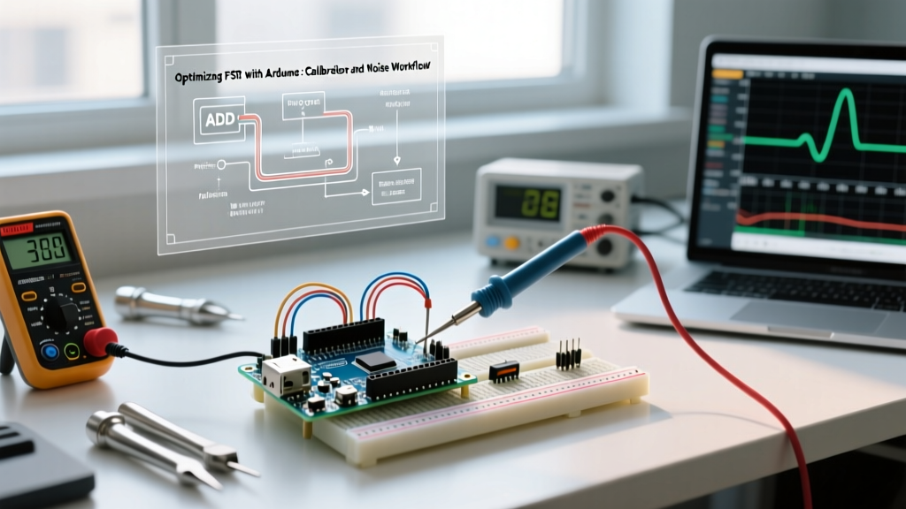

The FSR Integration Bottleneck
Force Sensitive Resistors (FSRs), like the industry-standard Interlink Electronics FSR402, are notorious for non-linear response curves, thermal drift, and mechanical hysteresis. When integrating an fsr with arduino, makers often default to the basic 10kΩ voltage divider and a simple analogRead() loop. While this approach is sufficient for blinking an LED or triggering a basic servo, it fails catastrophically in production environments, MIDI instruments, or ergonomic controllers where latency, repeatability, and signal stability are critical.
Workflow optimization requires shifting from a 'read and react' mindset to a structured engineering pipeline: mechanical decoupling, circuit tuning, ADC acceleration, and digital signal conditioning. As of 2026, while custom printed piezoresistive inks and capacitive alternatives exist, the classic polymer-thick-film FSR remains the most cost-effective rapid-prototyping solution (typically $7.50 to $9.00 per unit). This guide outlines a professional workflow to extract reliable, low-latency data from your FSR arrays.
Phase 1: Hardware and Mechanical Workflow
Tuning the Voltage Divider
Most hobbyist tutorials prescribe a 10kΩ pull-down resistor. This is mathematically suboptimal if your target force range isn't 0–10kg. The FSR402 drops from >1MΩ (no force) to ~250Ω (10kg force). To maximize the Arduino Uno's 10-bit ADC resolution (0-1023) within your specific operational window, you must calculate the optimal pull-down resistor ($R_{pull}$) based on the geometric mean of your target resistance range.
According to SparkFun's FSR Hookup Guide, the formula for the voltage divider output is $V_{out} = V_{cc} \times \frac{R_{pull}}{R_{fsr} + R_{pull}}$. By selecting the right resistor, you shift the ADC's peak resolution directly into your operational force band.
| Target Force Range | Approx. FSR Resistance | Optimal $R_{pull}$ | Peak ADC Resolution |
|---|---|---|---|
| Light Touch (0 - 1 kg) | 100kΩ - 30kΩ | 47kΩ | High (0-500g triggers) |
| Medium Grip (1 - 5 kg) | 30kΩ - 5kΩ | 10kΩ | Balanced (Standard) |
| Heavy Press (5 - 20 kg) | 5kΩ - 500Ω | 3.3kΩ | High (Max force mapping) |
| Impact / Percussion | 1kΩ - 100Ω | 1kΩ | Fast decay, high peak |
Mechanical Decoupling and Shear Mitigation
FSRs are highly sensitive to shear forces and point-loading, which cause permanent polymer degradation and erratic resistance spikes. Workflow rule: Never glue the FSR directly to a hard surface or allow a rigid actuator to press directly on the sensing dot.
Pro-Tip: Use a 'neoprene sandwich'. Place the FSR between a 2mm layer of neoprene foam and a rigid PLA/ABS backplate. The neoprene distributes point loads evenly across the active area and provides a mechanical return force, reducing hysteresis errors by up to 40% and extending component lifespan.
Phase 2: Accelerating the Arduino ADC Pipeline
The standard analogRead() function on an ATmega328P (Arduino Uno/Nano) takes approximately 104 microseconds. If you are polling an array of 16 FSRs for a MIDI drum pad or a robotic grip sensor, this introduces a 1.6ms latency bottleneck per sweep, entirely missing high-frequency impact transients.
Adjusting the ADC Prescaler
The ATmega328P ADC clock is derived from the system clock (16MHz) divided by a prescaler (default 128, yielding 125kHz). The ADC requires 13 clock cycles per conversion. By manipulating the ADCSRA register to a prescaler of 32 (500kHz ADC clock), you can reduce conversion time to ~26µs with negligible loss in 10-bit accuracy. This is a critical optimization detailed in the Arduino Analog Input Documentation.
// Optimized ADC Setup for High-Speed FSR Polling
void setup() {
  Serial.begin(115200);
  // Clear ADPS0, ADPS1, ADPS2, then set ADPS2 and ADPS0 for prescaler 32
  ADCSRA &= ~(bit(ADPS0) | bit(ADPS1) | bit(ADPS2));
  ADCSRA |= bit(ADPS2) | bit(ADPS0);
}

// Custom fast read function
int fastAnalogRead(byte pin) {
  ADMUX = (ADMUX & 0xF0) | (pin & 0x0F);
  ADCSRA |= bit(ADSC); // Start conversion
  while (ADCSRA & bit(ADSC)); // Wait for completion
  return ADC;
}
Phase 3: Digital Signal Conditioning
Raw FSR data is plagued by 50/60Hz mains hum, electromagnetic interference from nearby motors, and high-frequency mechanical bounce. Relying on raw ADC values will result in jittery outputs.
Exponential Moving Average (EMA) over SMA
A Simple Moving Average (SMA) requires storing an array of historical values, consuming precious SRAM and introducing phase lag. The Exponential Moving Average (EMA) requires only one stored variable and executes in a few clock cycles, making it ideal for real-time FSR workflows.
The formula is: EMA_today = (Value * α) + (EMA_yesterday * (1 - α)), where α is the smoothing factor (0.0 to 1.0).
float fsrEMA = 0.0;
const float alpha = 0.15; // Lower = smoother but more lag

void loop() {
  int rawValue = fastAnalogRead(A0);

  // EMA Calculation
  fsrEMA = (rawValue * alpha) + (fsrEMA * (1.0 - alpha));

  // Map the smoothed value
  int forceMapped = constrain(map(fsrEMA, 50, 900, 0, 255), 0, 255);
}
Implementing Hysteresis for Binary States
If you are using the FSR as a digital button or limit switch, mechanical creep (the gradual relaxation of the polymer under constant load) will cause rapid state toggling at the threshold. You must implement a dual-threshold hysteresis band.
- Trigger ON Threshold: 600 (Requires firm press)
- Trigger OFF Threshold: 450 (Requires significant release)
This 150-point deadband prevents oscillation when a user rests their finger lightly on the sensor.
Troubleshooting Edge Cases in Production
When moving from prototype to production, FSRs introduce specific failure modes that must be accounted for in your firmware and mechanical design:
- Thermal Drift: FSRs exhibit a resistance drift of roughly 1% to 2% per °C. If your device is used outdoors or near heat-generating components (like motor drivers), implement a software auto-zeroing routine that recalibrates the baseline 'no-load' value every 60 seconds during known idle states.
- Moisture Ingress: The polymer layers can delaminate or short out in high humidity. Always seal the FSR tail and active area with a thin layer of Kapton tape or conformal coating, ensuring you do not use rigid epoxies that restrict the sensor's flex.
- Cable Fatigue: The crimped tail of an FSR402 is fragile. Use a strain-relief loop and hot glue the first 1cm of the tail to your chassis to prevent copper trace tearing during repeated flexing.
Technology Selection Matrix: When to Abandon FSRs
While optimizing your workflow can mitigate many FSR limitations, they are not a universal solution. As noted in comprehensive sensor reviews like those found on Adafruit's FSR Guide, knowing when to pivot to a different technology saves weeks of debugging.
| Feature | FSR (e.g., Interlink 402) | Strain Gauge (w/ HX711) | Capacitive (e.g., MPR121) |
|---|---|---|---|
| Cost (2026) | ~$8.50 / unit | ~$3.00 / unit + amp | ~$2.50 / IC |
| Linearity | Poor (Logarithmic) | Excellent | N/A (Binary/Proximity) |
| Repeatability | ±15% variance | ±1% variance | Highly Repeatable |
| Best Use Case | Presence detection, rough grip | Precision scales, robotics | Touch buttons, sliders |
Summary Checklist for Production
To ensure your fsr with arduino integration is robust, run through this final workflow checklist before finalizing your PCB or enclosure design:
- [ ] Resistor Tuning: Calculated $R_{pull}$ based on target force, not default 10kΩ.
- [ ] ADC Speed: Prescaler adjusted to 32 for multi-sensor polling.
- [ ] Filtering: EMA implemented to eliminate mains hum and mechanical bounce.
- [ ] Hysteresis: Dual-threshold logic applied for binary triggers.
- [ ] Mechanics: Neoprene sandwich utilized to prevent shear and point-loading.
- [ ] Strain Relief: Sensor tails secured to prevent trace tearing.
By treating the FSR not just as a simple variable resistor, but as a complex electromechanical transducer requiring specific signal conditioning, you elevate your Arduino projects from unreliable prototypes to production-ready instruments.