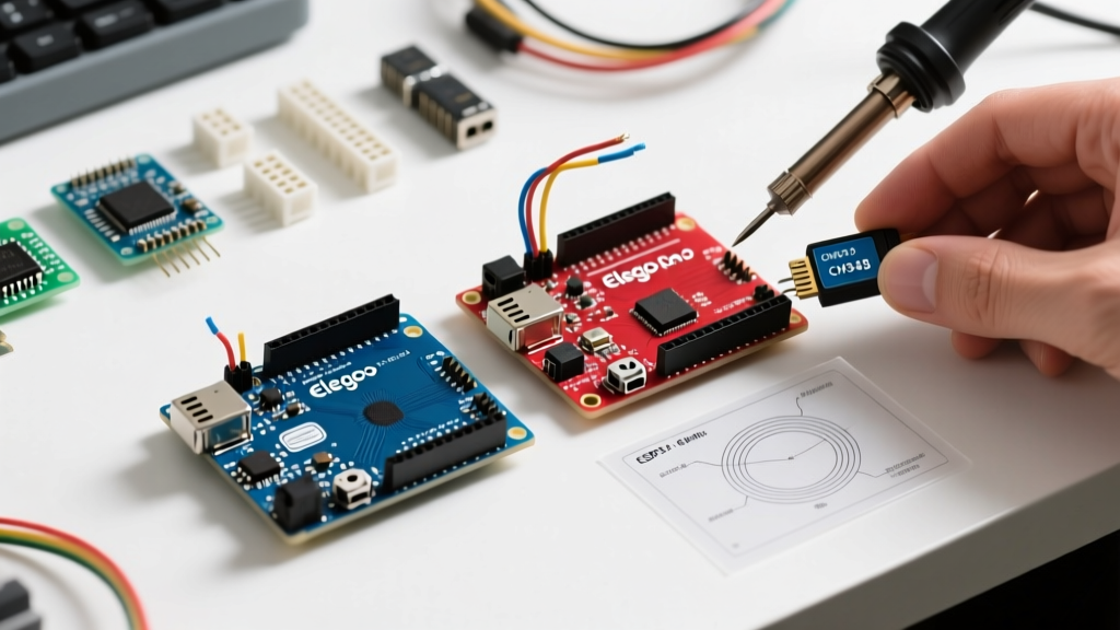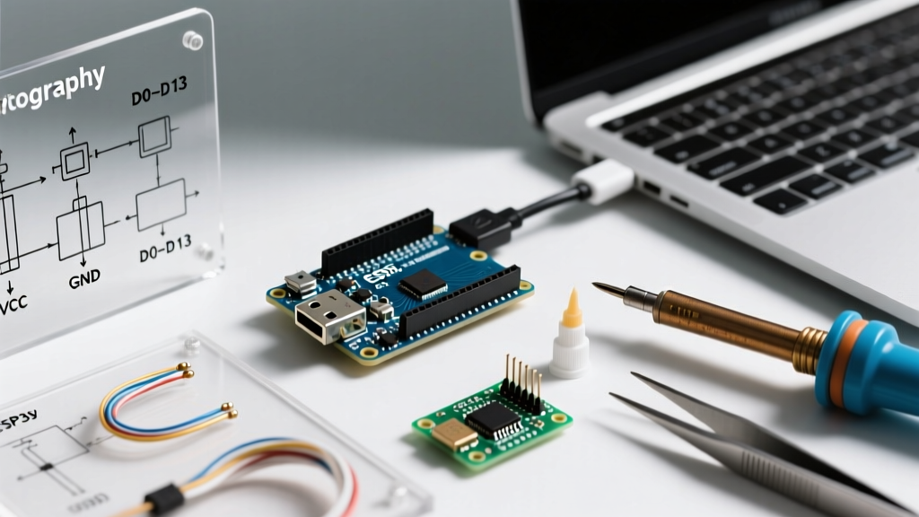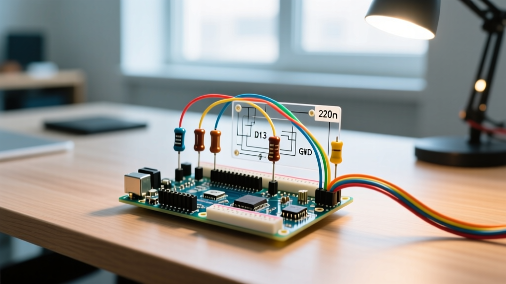

Every electronics maker begins their journey with the famous "Blink" sketch, but transitioning from a single onboard indicator to a custom Arduino LED light array introduces electrical engineering constraints that beginner tutorials often gloss over. Whether you are wiring standard 5mm through-hole indicators, high-power 3W star PCBs, or addressable WS2812B strips, understanding the physics of your microcontroller's GPIO pins is critical to preventing burnt traces and dim outputs.
This quick reference guide and FAQ provides exact resistor calculations, pin current limits, and advanced wiring topologies for your next lighting project in 2026.
The Golden Rules of Arduino LED Light Wiring
Rule 1: Never wire an LED directly to a GPIO pin without a current-limiting resistor (unless using an integrated driver like the WS2812B).
Rule 2: Always place the resistor on the anode (positive) side of the LED, though electrically it works on either side.
Rule 3: Never exceed 80% of a microcontroller pin's absolute maximum current rating to ensure long-term silicon reliability.
Quick Reference: Resistor Sizing for Common LEDs
Calculating the correct resistor requires Ohm's Law: R = (Vs - Vf) / If, where Vs is source voltage, Vf is the LED forward voltage, and If is the target forward current. Below is a cheat sheet for standard 5mm LEDs targeting a safe 20mA current.
| LED Color | Typical Vf | Target If | Resistor (5V Logic) | Resistor (3.3V Logic) |
|---|---|---|---|---|
| Red | 2.0V | 20mA | 150Ω | 68Ω |
| Green / Yellow | 2.1V | 20mA | 150Ω | 62Ω |
| Blue / White | 3.2V | 20mA | 100Ω | See Edge Case Below |
The 3.3V Blue/White LED Edge Case
If you are using an ESP32 or Arduino Due (3.3V logic), driving a blue or white LED (Vf = 3.2V) at 20mA is practically impossible directly from the pin. The mathematical headroom is only 0.1V (3.3V - 3.2V). At 20mA, this requires a 5Ω resistor. However, the internal output impedance of the GPIO pin (often 20Ω to 50Ω) will consume that voltage drop, resulting in a very dim light. Solution: Drop your target current to 5mA (using a 22Ω resistor) or use a logic-level MOSFET to switch the LED from a dedicated 5V rail.
Microcontroller Pin Limits: ATmega328P vs ESP32
According to the Microchip ATmega328P datasheet and official Arduino Digital Pins Documentation, understanding the difference between 'Absolute Maximum' and 'Recommended' ratings is the difference between a working prototype and a bricked board.
- ATmega328P (Arduino Uno/Nano): Absolute max per pin is 40mA. Recommended continuous current is 20mA. Total VCC/GND package limit is 200mA.
- ESP32 (Standard Modules): Absolute max per pin is 40mA, but recommended is strictly 10mA to 12mA for stable operation. Total package limit varies by module but generally hovers around 110mA for all GPIOs combined.
Pro Tip: If your Arduino LED light project requires more than 6 standard LEDs on a single Uno, you must use a transistor array (like the ULN2803) or shift registers (74HC595) to offload the current from the microcontroller's internal silicon.
Driving High-Power Arduino LED Lights (1W to 5W)
High-power LEDs mounted on star PCBs (common in flashlights and automotive lighting) draw between 350mA and 700mA. A GPIO pin cannot drive these. You must use a logic-level N-Channel MOSFET.
Recommended MOSFETs for 2026 Builds
- IRLB8721: Excellent for 3.3V logic (ESP32). Features an Rds(on) of just 4.5mΩ at Vgs=2.5V. Costs roughly $1.50 per unit.
- IRLZ44N: The classic maker standard. Great for 5V logic (Arduino Uno), but requires a full 5V gate signal to fully open the channel and prevent thermal throttling. Costs about $0.80 per unit.
Wiring Topology for High-Power LEDs
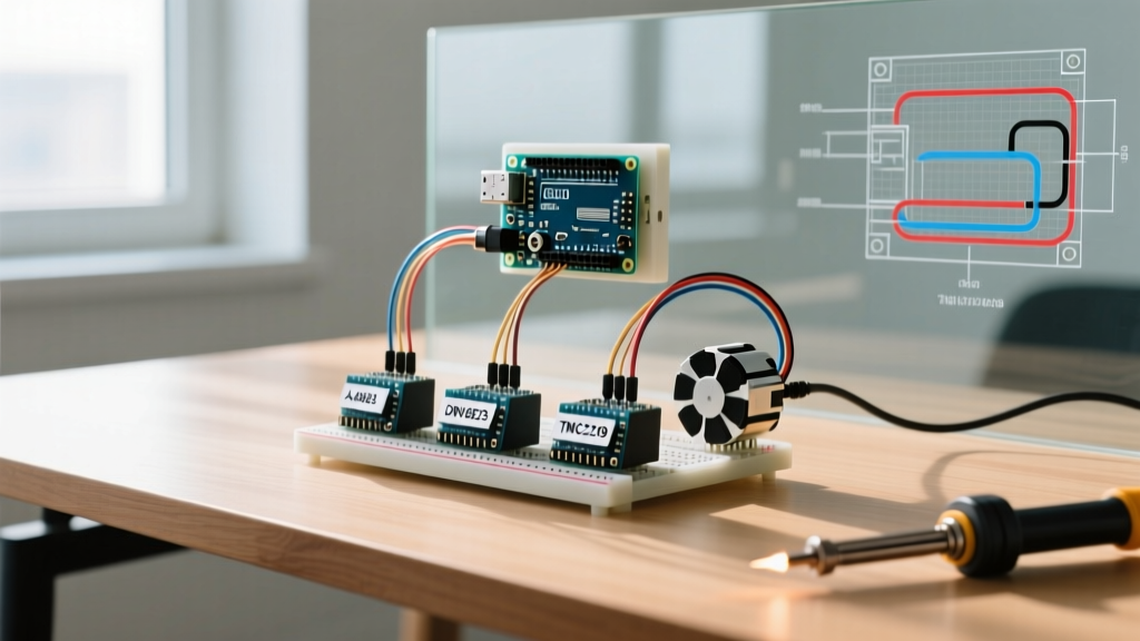
- Gate: Connect to Arduino PWM pin via a 220Ω resistor (prevents ringing).
- Gate to Ground: Add a 10kΩ pull-down resistor to ensure the LED stays off during microcontroller boot-up when pins are floating.
- Drain: Connect to the LED cathode (negative).
- Source: Connect to system ground.
- LED Anode: Connect to external power supply (e.g., 12V) via a constant-current LED driver or high-wattage power resistor.
Addressable LED Strips (WS2812B / SK6812)
Addressable LEDs have built-in constant-current drivers, eliminating the need for external resistors for the LEDs themselves. However, they introduce massive power delivery challenges. A standard WS2812B pixel draws roughly 60mA at full white (RGB 255,255,255).
If you wire a 1-meter strip of 60 LEDs, the total current draw is 3.6 Amps. The Arduino Uno's onboard 5V linear regulator is typically rated for 500mA to 800mA maximum (and that includes the board's own consumption). Wiring a 60-LED strip to the Uno's 5V pin will cause the thermal shutdown polyfuse to trip, or worse, melt the USB trace.
According to the Adafruit NeoPixel ÜberGuide, you must inject external power directly into the strip's power rails for any setup exceeding 15 pixels. Furthermore, a 1000µF electrolytic capacitor should be placed across the VCC and GND terminals at the start of the strip to buffer sudden current spikes and prevent voltage brownouts.
FAQ: Troubleshooting Common Failures
Why is my Arduino LED light glowing faintly when the pin is set to LOW?
This is usually caused by a floating gate if you are using a MOSFET, or induced electromagnetic voltage in long wire runs. If using a bare LED, ensure your code explicitly sets pinMode(pin, OUTPUT); in the setup() block. If the pin defaults to INPUT, it acts as a high-impedance antenna and can leak enough microamps to faintly illuminate high-efficiency modern LEDs.
Why does my Arduino reset every time the LED turns on?
This is a classic brownout condition. When a high-current LED (or strip) activates, it pulls the voltage rail down. If the 5V rail drops below the ATmega328P's brownout detection threshold (typically 4.3V or 2.7V depending on the fuse settings), the microcontroller will trigger a hardware reset. Fix: Separate the LED power supply from the Arduino power supply, ensuring they share a common Ground (GND) reference, but do not route the LED current through the Arduino's VIN or 5V pins.
Can I use PWM (analogWrite) to dim any Arduino LED light?
Yes, but be aware of the hardware timer frequencies. On the Arduino Uno, pins 5 and 6 operate at 980Hz, while pins 3, 9, 10, and 11 operate at 490Hz. If you are using PWM to drive a MOSFET for a high-power LED, the 490Hz frequency can sometimes cause audible whining in the MOSFET or inductor components. For silent, flicker-free dimming, consider upgrading to an ESP32, which allows you to configure the ledcSetup() frequency up to 20kHz, well above human hearing range.
What is the most cost-effective way to drive 50 individual standard LEDs?
Do not use 50 individual GPIO pins or 50 individual resistors. Instead, use a technique called Charlieplexing, or wire them in an 8x8 matrix using a MAX7219 LED display driver IC. The MAX7219 handles all the current limiting and multiplexing internally via SPI, requiring only 3 data wires from your Arduino and costing less than $3.00 on the open market.