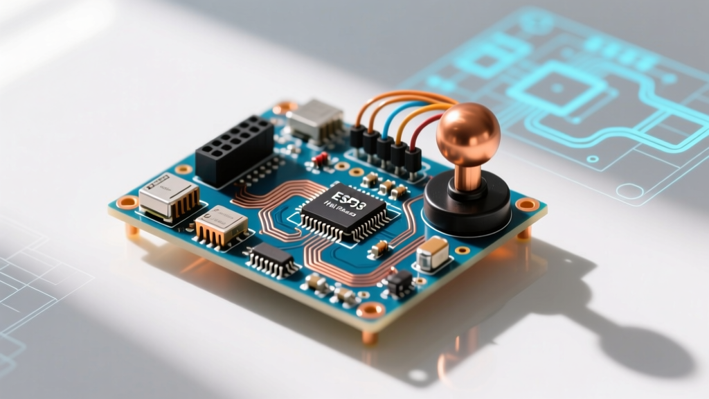

The End of Stick Drift: Why Migrate Your Joystick Hardware?
If you have been building DIY gamepads, robotic arms, or RC transmitters, you have likely relied on the ubiquitous KY-023 analog joystick module. While these inexpensive components are excellent for initial prototyping, their carbon-track potentiometers are notorious for developing 'stick drift' and dead zones after just a few thousand mechanical cycles. As of 2026, the maker community has largely shifted toward magnetic sensing technologies for critical input devices. Upgrading your Arduino joy stick setup to a Hall-effect or TMR (Tunnel Magnetoresistance) sensor module is no longer just a premium luxury; it is a practical necessity for any project requiring long-term reliability and precision.
This migration guide will walk you through the hardware swap, wiring adjustments, and firmware updates required to replace legacy analog potentiometer joysticks with modern, drift-free magnetic alternatives. Whether you are updating an existing CNC controller or building a high-fidelity drone transmitter, this guide provides the exact specifications and code adaptations you need.
Legacy vs. Modern: Joystick Module Comparison Matrix
Before desoldering your current setup, it is crucial to understand the electrical and mechanical differences between the legacy modules and their modern replacements. The table below outlines the primary options available to makers today.
| Feature | KY-023 (Legacy Analog) | KY-052 (I2C Digital) | Hall-Effect / TMR Analog (2026 Standard) |
|---|---|---|---|
| Sensing Tech | Carbon-Track Potentiometer | Digital I2C Encoder | Linear Hall / TMR Magnetic Sensor |
| Lifespan | ~100,000 cycles | ~1,000,000 cycles | Infinite (No physical contact) |
| Stick Drift | High (Prone to wear) | None | None |
| Output Type | 0V - VCC (Analog) | Digital I2C Bus | 0V - VCC (Analog) or PWM |
| Avg. Cost (2026) | $1.50 - $2.50 | $6.00 - $8.00 | $8.00 - $14.00 |
For most DIY analog-to-digital conversions, the Hall-Effect Analog Module is the ideal drop-in replacement. It maintains the standard voltage-divider output expected by your microcontroller's ADC (Analog-to-Digital Converter) while entirely eliminating the mechanical wiper that causes signal noise and drift.
Hardware Migration: Swapping the Modules
Migrating the physical hardware requires attention to power rail stability. Legacy potentiometers are highly forgiving of noisy power supplies because they simply act as variable resistors. Hall-effect sensors, however, contain active internal amplifiers that require a clean, regulated voltage reference to output a stable center-point reading.
Step 1: Pinout Mapping and Rewiring
The standard KY-023 features five pins: GND, +5V, VRx, VRy, and SW (Switch). Most generic Hall-effect analog joysticks (such as those based on the SS49E linear Hall sensor or newer TMR equivalents) utilize a similar pinout, but with critical distinctions regarding voltage limits.
- VCC / +5V: Verify your new module's operating voltage. While many are 5V tolerant, high-precision TMR modules designed for 3.3V logic (like those paired with ESP32 or Raspberry Pi Pico) must be connected to the 3.3V rail. Supplying 5V to a 3.3V Hall module will destroy the internal amplifier and yield clipped, non-linear data.
- GND: Connect to a common ground. For optimal noise rejection, route this ground directly to the microcontroller's primary analog ground plane rather than daisy-chaining it through high-current motor driver grounds.
- X-Out / Y-Out: Connect to your microcontroller's ADC pins. Unlike legacy pots, you do not need to worry about the physical orientation of the X and Y axes; these can be easily swapped in software if the module is mounted at an awkward angle.
- SW (Select Switch): Many premium Hall modules omit the mechanical Z-axis push-button to save space and reduce points of failure. If your project relies on a joystick click, you may need to wire a separate momentary tactile switch to a digital pin with an internal pull-up resistor.
Step 2: Adding Decoupling Capacitors
Because Hall sensors are active semiconductor devices, they are susceptible to high-frequency EMI (Electromagnetic Interference) from nearby brushless motors or switching regulators. Solder a 100nF (0.1µF) ceramic capacitor directly across the VCC and GND pins of the new joystick module. This localized energy reservoir filters out transient voltage spikes that would otherwise manifest as 'jitter' in your serial monitor readings.
Firmware Upgrade: Implementing Deadzones and Curves
When you first upload your old sketch to the new hardware, you might notice that the joystick never quite returns to a perfect zero, or it feels overly sensitive near the center. This is normal. Legacy carbon pots have a wide mechanical deadzone, whereas magnetic sensors are incredibly precise and will pick up microscopic magnetic variances.
To adapt your firmware, you must implement a software deadzone and an exponential response curve. For a deeper understanding of how your microcontroller samples these voltages, refer to the Arduino analogRead() documentation to ensure your ADC resolution settings match your hardware.
The 2026 Standard Calibration Code
Below is a robust C++ function designed for 10-bit ADCs (0-1023). It applies a 10% deadzone to eliminate center-point jitter and maps the remaining range to a smooth -100 to +100 output scale.
// Define calibration constants based on multimeter/serial readings
const int RAW_CENTER = 512; // The exact ADC reading when stick is at rest
const int RAW_MIN = 15;     // ADC reading at full physical throw
const int RAW_MAX = 1008;   // ADC reading at opposite full throw
const float DEADZONE_PCT = 0.10; // 10% deadzone

int processHallAxis(int rawInput) {
  int centeredValue = rawInput - RAW_CENTER;
  int deadzoneThreshold = (int)(RAW_CENTER * DEADZONE_PCT);

  // Apply Deadzone
  if (abs(centeredValue) < deadzoneThreshold) {
    return 0;
  }

  // Calculate magnitude outside the deadzone
  float magnitude = abs(centeredValue) - deadzoneThreshold;
  float maxMagnitude = (centeredValue > 0) ? (RAW_MAX - RAW_CENTER - deadzoneThreshold) : (RAW_CENTER - RAW_MIN - deadzoneThreshold);

  // Normalize to 0.0 - 1.0
  float normalized = magnitude / maxMagnitude;
  if (normalized > 1.0) normalized = 1.0;

  // Apply Exponential Curve for finer control at low speeds (Cubed)
  float curved = normalized * normalized * normalized;

  // Scale to -100 to +100 and restore sign
  int finalOutput = (int)(curved * 100.0);
  return (centeredValue > 0) ? finalOutput : -finalOutput;
}
By applying a cubic curve (normalized * normalized * normalized), you give the user high precision for slow, micro-movements near the center, while still allowing full 100% output when the stick is pushed to the physical edge. This mimics the feel of premium commercial gamepads and high-end drone gimbals.
Edge Case: Migrating from ATmega328P to ESP32
A common scenario in 2026 is migrating an older Arduino Uno (ATmega328P) project to an ESP32 for Wi-Fi/Bluetooth capabilities. If you are moving your Arduino joy stick interface to an ESP32, you will encounter a major hardware edge case: ADC Non-Linearity.
The ESP32's built-in ADC (specifically on pins GPIO32 through GPIO39) is notoriously non-linear at the extreme ends of the 0-3.3V spectrum. It often saturates around 3.1V and struggles to read cleanly below 0.15V. If you plug a highly linear Hall-effect joystick into an ESP32, you will lose the outer 10% of your physical throw range in software.
Solutions for ESP32 ADC Limitations
- Use the ESP32's Internal Calibration eFuse: Espressif provides the
esp_adc_callibrary, which reads factory calibration data burned into the chip's eFuses to correct the raw readings. This fixes the mid-range non-linearity but cannot fix the hardware saturation at the voltage rails. - Voltage Divider Scaling: Place a simple resistor voltage divider on the X and Y output lines to scale the 0-3.3V Hall output down to 0.1V - 3.0V. This keeps the signal entirely within the ESP32's linear ADC sweet spot.
- External I2C ADC (Recommended): For professional-grade robotics or CNC pendants, bypass the ESP32's internal ADC entirely. Use an ADS1115 16-bit I2C ADC module (approx. $4.00). This provides flawless, noise-free, 16-bit resolution and completely eliminates ESP32 ADC headaches. You can learn more about integrating external breakouts via the Adafruit ADC Breakout Guide.
Pro-Tip for RF Interference: If your joystick is connected via a cable longer than 15cm, the analog wires will act as antennas, picking up RF noise from the ESP32's Wi-Fi antenna. Always use shielded twisted-pair cable for the X and Y analog signals, and connect the shield drain wire to GND at the microcontroller end only.
Final Calibration and Testing Checklist
Before sealing your project enclosure, run through this final migration checklist to ensure your new magnetic joystick is performing optimally:
- Center-Point Verification: Power the device and let it sit untouched for 5 minutes. Monitor the serial output. The value should not drift by more than ±1 ADC unit.
- Gimbal Bind Check: Push the joystick to the extreme top-left corner. Ensure the X and Y axes do not exhibit 'cross-talk' (where moving X slightly alters the Y value due to magnetic field bleeding). High-quality 2026 TMR modules have internal shielding to prevent this, but cheap clones may require a software cross-talk compensation matrix.
- Thermal Stability: Hall-effect sensors have a slight temperature coefficient. If your project operates in an unheated garage or an outdoor enclosure, test the joystick at both 5°C and 35°C. You may need to implement a software temperature offset using an onboard thermistor if extreme precision is required across wide thermal swings.
Upgrading from a legacy carbon-track module to a modern Hall-effect or TMR sensor is one of the highest-ROI improvements you can make to a DIY controller. By addressing the power delivery, implementing proper software deadzones, and accounting for microcontroller-specific ADC quirks, your Arduino joy stick project will achieve commercial-grade reliability and a premium tactile response.