
The Architecture of Conditional Logic in Embedded C++
At the core of every responsive microcontroller project lies the Arduino if then else statement. While it is a fundamental C++ construct, configuring it correctly for embedded systems requires a deeper understanding of hardware constraints, compiler behavior, and sensor physics. Unlike desktop applications, where a misconfigured conditional might simply cause a UI glitch, a poorly structured conditional on an Arduino Uno R4 Minima or a Nano ESP32 can lead to missed sensor interrupts, memory bloat, or catastrophic hardware timing failures.
This configuration guide moves beyond basic syntax. We will explore how to properly configure thresholds, manage hardware pull-up inversions, avoid the 'arrow anti-pattern' in nested logic, and implement non-blocking time deltas. According to the official Arduino if() reference, the statement executes a block of code only if a specified condition evaluates to true. However, how that condition is evaluated at the silicon level dictates the reliability of your entire sketch.
Compiler Behavior and Execution Time on 8-bit vs 32-bit MCUs
When you write an if/else block, the GCC compiler translates it into assembly jump instructions. On legacy 8-bit AVR boards (like the classic Uno R3), the processor lacks advanced branch prediction. This means the order of your else if chains directly impacts execution time.
- AVR (8-bit): Evaluates conditions sequentially. Place the most statistically likely condition at the top of the chain to save clock cycles.
- ARM Cortex-M4 (32-bit, e.g., Uno R4): Features hardware branch prediction. While order matters less for raw speed, organizing by logical priority still improves code readability and cache efficiency.
Configuring Analog Thresholds: The Voltage-to-ADC Matrix
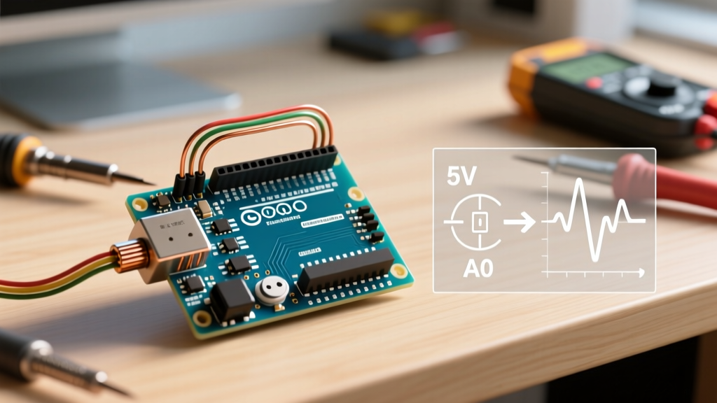
The most common use case for the Arduino if then else structure is evaluating analog sensor data. A frequent configuration error is hardcoding magic numbers without accounting for the board's ADC (Analog-to-Digital Converter) resolution or reference voltage.
Below is a configuration matrix for common sensors, mapping physical thresholds to the correct ADC values for both 10-bit (5V AVR) and 12-bit (3.3V ESP32) architectures.
| Sensor Type | Physical Trigger | Voltage Target | 10-bit ADC (5V Uno) | 12-bit ADC (3.3V ESP32) | Configuration Snippet |
|---|---|---|---|---|---|
| LDR (Light) | Room Darkness | < 2.0V | < 409 | < 2488 | if (ldrVal < 409) |
| NTC Thermistor | Overheat (> 60°C) | > 3.5V | > 716 | > 4352 | if (tempVal > 716) |
| MQ-2 Gas | Smoke Detected | > 1.5V | > 307 | > 1861 | if (gasVal > 307) |
| Potentiometer | Midpoint Detent | ~2.5V | 490 - 530 | 3030 - 3150 | if (pot > 490 && pot < 530) |
Pro-Tip for ESP32 Configurations: The ESP32's ADC is notoriously non-linear at the extremes (near 0 and 4095). When configuring your if then else thresholds on an ESP32, restrict your logical evaluation to the 150–3900 range to ensure accurate sensor triggering.
Digital Inputs and the INPUT_PULLUP Inversion Trap
When configuring digital buttons or limit switches, floating pins are the enemy of reliable logic. A floating pin acts as an antenna, picking up electromagnetic interference and causing your if statement to trigger randomly. The hardware solution is to use internal pull-up resistors via pinMode(pin, INPUT_PULLUP).
However, this introduces a logical inversion that trips up many makers. As detailed in the Arduino Digital Pins documentation, enabling the internal pull-up (typically 20kΩ to 50kΩ) ties the pin to VCC (HIGH) by default. When the button is pressed, it connects to ground (LOW).
Correcting the Logic Inversion
Your Arduino if then else configuration must be inverted to match the hardware reality:
// INCORRECT: Will trigger when the button is RELEASED
if (digitalRead(buttonPin) == HIGH) {
  triggerAlarm();
}

// CORRECT: Triggers when the button is PRESSED (pulled to GND)
if (digitalRead(buttonPin) == LOW) {
  triggerAlarm();
} else {
  standbyMode();
}
Structuring Nested Conditionals: Avoiding the Arrow Anti-Pattern
As projects grow, makers often nest if statements inside one another, creating a shape that resembles a right-pointing arrow. This 'Arrow Anti-Pattern' consumes excessive SRAM for stack frames and makes debugging nearly impossible.
The Guard Clause Configuration
Instead of nesting, configure your logic using Guard Clauses (early exits). This flattens your code and optimizes the compiler's output.
// BAD: Deeply Nested (Arrow Pattern)
if (systemArmed) {
  if (motionDetected) {
    if (batteryLevel > 20) {
      soundAlarm();
    } else {
      sendLowBatteryAlert();
    }
  }
}

// GOOD: Flattened with Guard Clauses
if (!systemArmed) return;
if (!motionDetected) return;

if (batteryLevel <= 20) {
  sendLowBatteryAlert();
  return;
}
soundAlarm();
Time-Based Conditionals: Configuring millis() Deltas
Using delay() inside an if block halts the microcontroller, preventing it from reading other sensors or maintaining communication protocols like I2C or MQTT. The correct configuration relies on the millis() function to track time deltas.
Handling the 50-Day Rollover Edge Case
The millis() timer is an unsigned long that overflows and resets to zero approximately every 49.7 days. If your if then else statement uses simple subtraction without unsigned math, your system will crash or behave erratically on day 50.
unsigned long previousMillis = 0;
const long interval = 5000; // 5 seconds

void loop() {
  unsigned long currentMillis = millis();

  // CORRECT CONFIGURATION: Handles rollover automatically
  if (currentMillis - previousMillis >= interval) {
    previousMillis = currentMillis;
    toggleRelay();
  } else {
    // Perform non-blocking background tasks
    readTemperature();
  }
}
Edge Cases and Troubleshooting Ghost Triggers
Even with perfect syntax, physical hardware introduces noise. Here is how to configure your logic to handle real-world edge cases.
1. Switch Bounce Debouncing
Mechanical switches physically bounce when pressed, creating multiple rapid HIGH/LOW transitions over 5 to 50 milliseconds. If your if statement increments a counter on a button press, one press might register as five.
- Software Fix: Implement a 50ms lockout timer using the
millis()delta method shown above. - Hardware Fix: Add a 0.1µF ceramic capacitor across the switch terminals to filter the high-frequency bounce.
2. Analog Hysteresis (The Chatter Killer)
When an analog sensor hovers exactly at your configured threshold (e.g., an LDR reading exactly 409), minor electrical noise will cause the if then else statement to rapidly flip between true and false, causing relay chatter or LED flickering.
The Solution: Configure hysteresis by creating two distinct thresholds—an upper and a lower bound.
bool isDark = false;

void loop() {
  int ldrVal = analogRead(A0);

  // Hysteresis Configuration
  if (ldrVal < 380) {       // Lower threshold to turn ON
    isDark = true;
  } else if (ldrVal > 420) { // Upper threshold to turn OFF
    isDark = false;
  }
  // Notice: If ldrVal is between 380 and 420, the state DOES NOT CHANGE

  if (isDark) {
    digitalWrite(LED_BUILTIN, HIGH);
  } else {
    digitalWrite(LED_BUILTIN, LOW);
  }
}
Summary Checklist for Production Sketches
Before flashing your final firmware, verify your conditional logic against this configuration checklist:
- ADC Scaling: Are your analog thresholds matched to the specific board's bit-depth (10-bit vs 12-bit) and reference voltage?
- Pull-Up Inversion: Are digital inputs using
INPUT_PULLUPevaluated againstLOWfor active states? - Non-Blocking: Are all timing-based
ifstatements usingmillis()deltas instead ofdelay()? - Hysteresis: Do analog sensors operating near environmental thresholds have a deadband to prevent chatter?
- Variable Types: Are time-tracking variables explicitly declared as
unsigned longto prevent rollover math errors?
By treating the Arduino if then else statement not just as a coding syntax, but as a hardware-aware configuration tool, you ensure your embedded projects remain stable, responsive, and resilient against the physical realities of electronic noise and timing constraints.