
Introduction to Inertial Measurement Units in Embedded Systems
Integrating motion tracking into your microcontroller projects requires a solid understanding of both hardware protocols and sensor physics. When you interface an Arduino with IMU (Inertial Measurement Unit) modules, you are essentially giving your project the ability to perceive its own orientation, acceleration, and rotational velocity in 3D space. Whether you are building a self-balancing robot, a drone flight controller, or a motion-capture glove, selecting the right sensor and wiring it correctly is the difference between a responsive system and one plagued by drift and noise.
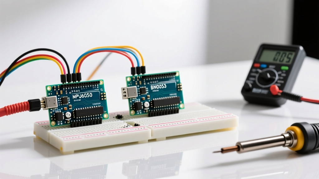
This comprehensive guide will walk you through the exact hardware wiring, I2C bus considerations, and software implementation required to get reliable data from the two most popular IMU families on the market: the legacy InvenSense MPU6050 and the advanced Bosch BNO055.
Sensor Selection: Raw MEMS vs. On-Chip Sensor Fusion
Before soldering a single header pin, you must decide whether your application requires raw sensor data or pre-calculated absolute orientation. In 2026, the maker market is dominated by three primary tiers of IMU breakout boards.
| Feature | MPU6050 (InvenSense) | BNO055 (Bosch) | BHI260AP (Bosch) |
|---|---|---|---|
| Axes | 6 (Accel/Gyro) | 9 (Accel/Gyro/Mag) | 6 (Accel/Gyro) + AI |
| On-board Fusion | No (Requires host MCU) | Yes (Cortex-M0) | Yes (Fuser Core) |
| Typical Price (2026) | $2.50 - $4.00 | $35.00 - $45.00 | $15.00 - $22.00 |
| I2C Address | 0x68 / 0x69 | 0x28 / 0x29 | 0x28 / 0x29 |
| Output Data | Raw Vectors | Quaternions / Euler | Raw / Custom Algo |
The MPU6050 is a 6-axis raw MEMS sensor. It is incredibly cheap but lacks a magnetometer, meaning it cannot determine absolute heading (yaw) relative to magnetic north. Furthermore, your Arduino must handle the heavy mathematical lifting of sensor fusion (like Kalman or Madgwick filters) to combine accelerometer and gyroscope data, which can consume valuable clock cycles on an ATmega328P.
The BNO055, on the other hand, is a System-in-Package (SiP) that includes an ARM Cortex-M0 processor dedicated exclusively to running Bosch's proprietary sensor fusion algorithms. According to the official Bosch Sensortec documentation, the BNO055 outputs highly stable, drift-free quaternions directly over I2C, entirely offloading the math from your main microcontroller.
Hardware Wiring: The I2C Bus and Level Shifting
The most common point of failure when connecting an Arduino with IMU hardware is ignoring logic level voltages. Most modern IMU breakout boards operate strictly at 3.3V. If you are using a 5V Arduino Uno or Mega, feeding 5V directly into the SDA and SCL lines of a BNO055 will eventually degrade or destroy the sensor's I2C transceiver.
Step-by-Step Wiring Guide
- Power (VIN/VCC): Connect the breakout board's VCC pin to the Arduino's 3.3V output. Do not use the 5V pin unless your specific breakout board explicitly features an onboard 3.3V voltage regulator (like the Adafruit BNO055 breakout).
- Ground (GND): Connect GND to GND. A common ground is mandatory for I2C signal reference.
- Data (SDA): Connect the sensor's SDA to the Arduino's SDA (A4 on Uno, Pin 20 on Mega). Crucial: If using a 5V Arduino, route this through a bidirectional logic level shifter (e.g., NXP PCA9306 or a basic BSS138 MOSFET module).
- Clock (SCL): Connect the sensor's SCL to the Arduino's SCL (A5 on Uno, Pin 21 on Mega), also through the logic level shifter if operating at 5V.
Expert Note on Pull-Up Resistors: The I2C specification requires pull-up resistors on the SDA and SCL lines. Most premium breakout boards include 4.7kΩ or 10kΩ onboard pull-ups. However, ultra-cheap MPU6050 clone boards often omit them. If your I2C scanner returns no devices, measure the resistance between SDA and VCC. If it reads infinite, you must solder external 4.7kΩ resistors between the SDA/SCL lines and the 3.3V rail.
Software Implementation and I2C Scanning
Before loading complex sensor fusion libraries, always verify the physical connection using an I2C scanner sketch. This prevents hours of debugging code when the actual issue is a cold solder joint or a missing pull-up resistor. The Arduino Wire Library Reference provides the foundational `Wire.begin()` and `Wire.requestFrom()` functions used to probe the bus.
Once the sensor is detected at its hex address (usually 0x28 for the BNO055), you can utilize the Adafruit BNO055 library. As detailed in the Adafruit Learning System, initializing the sensor in NDOF (Nine Degrees of Freedom) mode allows the internal Cortex-M0 to calibrate the magnetometer, accelerometer, and gyroscope simultaneously.
Understanding Quaternions vs. Euler Angles
When reading data from the BNO055, you have the option to request Euler angles (Heading, Roll, Pitch) or Quaternions (X, Y, Z, W). Always use Quaternions for robotics and stabilization. Euler angles suffer from "Gimbal Lock," a mathematical singularity that occurs when the pitch approaches ±90 degrees, causing the yaw and roll axes to align and resulting in erratic, unpredictable outputs. Quaternions represent 3D rotations using four-dimensional complex numbers, entirely avoiding Gimbal Lock and providing smooth, continuous rotation data that can be fed directly into a PID controller.
Mechanical Mounting and Vibration Isolation
A frequently overlooked aspect of IMU integration is physical mounting. MEMS accelerometers are essentially microscopic spring-mass systems etched into silicon. They are extraordinarily sensitive to high-frequency vibrations from DC motors, propellers, or even nearby speakers.
- Center of Mass Alignment: Mount the IMU as close to the rotational center of mass of your robot or drone as possible. If the IMU is offset from the center of rotation, every yaw or pitch movement will induce centripetal acceleration, which the accelerometer will falsely interpret as linear movement, corrupting your sensor fusion.
- Damping Materials: Do not hot-glue the IMU directly to a vibrating chassis. Use Sorbothane pads, double-sided acrylic foam tape (like 3M VHB), or silicone O-rings to mechanically low-pass filter high-frequency vibrations before they reach the silicon die.
- Magnetic Interference: If using a 9-axis sensor, keep the IMU at least 5 centimeters away from high-current ESCs, DC motor brushes, and neodymium magnets. Ferrous metals in the chassis will cause "hard iron" and "soft iron" distortion, warping the magnetometer's spherical calibration into an ellipsoid and ruining your absolute heading.
Troubleshooting Common Edge Cases
1. The Wire Library Hangs on `endTransmission()`
If your Arduino completely freezes when attempting to read the IMU, the I2C bus has likely locked up. This happens when the SDA line is pulled low by the sensor, but the master (Arduino) fails to send the correct clock pulses to release it. Fix: Implement a software I2C reset routine in your `setup()` function that manually toggles the SCL pin as a GPIO output 9 times to force the slave device to release the SDA line before calling `Wire.begin()`.
2. Magnetometer Calibration Never Completes
The BNO055 requires physical movement to calibrate its magnetometer. The system status register will show a calibration value from 0 to 3. If it remains stuck at 0, you are likely operating in an environment with severe magnetic distortion, or you are not providing the necessary 3D figure-eight motion required for the internal algorithm to map the local magnetic field sphere.
3. High-Frequency Noise in Static Readings
If your accelerometer shows ±0.2g of noise while sitting perfectly still on a desk, check your power supply. Switching voltage regulators (buck converters) on cheap Arduino clones introduce massive voltage ripple onto the 3.3V rail. Because MEMS sensors use ratiometric analog-to-digital conversion, power supply ripple translates directly into acceleration noise. Add a 100µF tantalum capacitor and a 0.1µF ceramic capacitor in parallel across the VCC and GND pins of the IMU breakout to filter high-frequency switching noise.
Summary
Successfully pairing an Arduino with IMU hardware requires respecting the physics of the sensor, the electrical limits of the I2C bus, and the mathematics of 3D rotation. By choosing the right sensor architecture for your processing needs, implementing proper 3.3V logic level shifting, and mechanically isolating the module from high-frequency vibrations, you can achieve professional-grade motion tracking in your DIY embedded projects.