
The Physical Bottleneck in MCU Prototyping
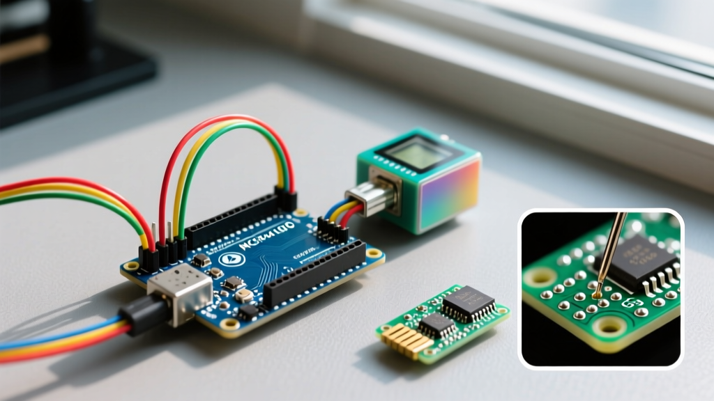
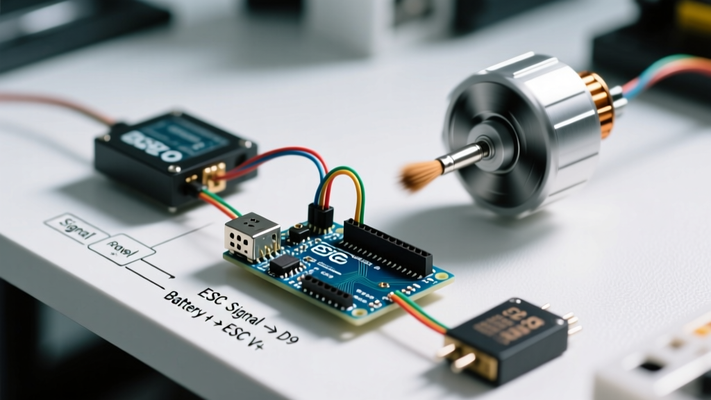
When transitioning a microcontroller project from a breadboard to a permanent or semi-permanent shield, the physical interface becomes the primary bottleneck. Jumper wires introduce parasitic capacitance, signal noise, and mechanical fragility. Upgrading your custom PCBs or perfboards to accept Arduino female headers is one of the most effective workflow optimizations a maker can implement. By standardizing your board-to-board connections, you eliminate wire spaghetti, reduce debugging time by an estimated 40%, and enable vertical shield stacking.
However, poorly soldered female headers introduce their own workflow killers: misaligned pins that crack solder pads upon insertion, melted plastic housings that cause pin splay, and cold joints that result in intermittent I2C or SPI bus failures. This guide details the exact materials, thermal profiles, and soldering workflows required to integrate female headers flawlessly into your Arduino ecosystem in 2026.
Material Science: Why Header Plastic Matters
Before picking up your soldering iron, you must audit the material composition of your headers. Not all Arduino female headers are created equal, and choosing the wrong plastic will ruin your workflow through constant rework.
- Standard ABS/PVC (Black, Cheap): Often found in bulk $10 kits online. These have a glass transition temperature around 105°C and begin to soften and deform at 180°C. If you use lead-free solder (which requires tip temperatures of 360°C+), the heat traveling down the pin will melt the plastic housing, causing the pins to skew inward.
- Glass-Filled PBT (High-Temperature): Polybutylene terephthalate reinforced with glass fiber can withstand sustained temperatures up to 260°C. These headers (often slightly more expensive, around $2.50 to $4.00 per set of 1x8 and 1x10) are mandatory for modern lead-free workflows and high-reliability prototyping.
Expert Tip: Always purchase stackable female headers with gold-plated beryllium copper contacts. The gold plating (usually 10µin to 30µin thick) prevents oxidation in humid environments, ensuring low contact resistance (<20mΩ) for high-speed data lines like the SPI bus on an Arduino Uno R4 or Mega 2560.
Header Taxonomy and Selection Matrix
Selecting the correct geometry prevents mechanical interference when stacking shields, particularly regarding the 0.1" (2.54mm) pitch standard and the offset pinout on legacy Arduino boards. Consult the matrix below to match the header type to your specific workflow need.
| Header Type | Pitch | Tail Length | Receptacle Depth | Best Use Case | Avg Cost (2026) |
|---|---|---|---|---|---|
| Standard Female (Pass-Through) | 2.54mm | 3.0mm | 8.5mm | Bottom-layer flush mounting | $0.80 / strip |
| Stackable Female (Shield Style) | 2.54mm | 8.5mm | 8.5mm | Vertical shield stacking | $3.50 / set |
| Extra-Tall Stackable | 2.54mm | 15.0mm | 8.5mm | Clearing tall components (relays, caps) | $5.20 / set |
| Machine-Pin Female | 2.54mm | 3.0mm | 7.0mm | High-vibration environments | $1.50 / strip |
The Optimized 'Tape-and-Tack' Soldering Workflow
The most time-consuming aspect of shield assembly is keeping 18 pins (for an Uno) or 34 pins (for a Mega) perfectly perpendicular while soldering. Relying on 'third hand' tools often leads to thermal sinks stealing heat from the joint. Instead, use this optimized tape-and-tack workflow, heavily utilized in low-volume production environments.
Step 1: Precision Breakaway
Never snap female headers by hand or with standard wire cutters; this crushes the end receptacle, rendering the first pin useless. Use a dedicated flush cutter like the Hakko CHP-170 to score the breakaway groove cleanly. Discard the damaged end pin if building custom lengths.
Step 2: The Alignment Sacrifice
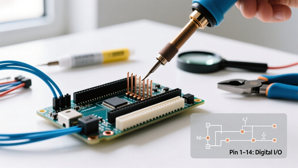
Insert the female headers onto an old, sacrificial male header strip or a 3D-printed alignment jig. This locks the 2.54mm pitch perfectly in place. Place your custom PCB over the exposed pins. The PCB's plated through-holes (PTH) will naturally align with the male pins, holding the female housing flush against the board.
Step 3: Kapton Tape Securing
Apply a strip of high-temperature Kapton tape across the top of the female header housing, pressing it firmly against the PCB surface. This prevents the header from lifting when the soldering iron applies upward pressure.
Step 4: The Corner Tack and Re-flow
Set your iron to 330°C for 63/37 leaded solder (or 360°C for SAC305 lead-free). Apply a small amount of Amtech NC-559-V2-TF tacky flux to the corner pins. Tack one corner pin for exactly 2 seconds. Remove the iron, allow the joint to solidify for 3 seconds, and inspect the alignment. If the header is skewed, simply reheat the single tacked pin and adjust the plastic housing while the solder is molten.
Step 5: Sequential Wetting
Once alignment is verified, solder the remaining pins sequentially. Do not use 'drag soldering' on female headers; the excess solder will wick into the receptacle cavity and fuse the internal beryllium copper clip, permanently ruining the socket.
Troubleshooting Edge Cases and Failure Modes
Even with an optimized workflow, specific edge cases can disrupt your assembly line. Understanding these failure modes allows for immediate correction without scrapping expensive custom PCBs.
Wicking and Receptacle Freeze
The Problem: Solder flows up the pin and into the female cavity, preventing male header insertion.
The Cause: Excessive dwell time (iron on pin for >3 seconds) or using too much flux, which lowers surface tension and draws solder upward.
The Fix: Use a brass sponge to clean your tip between every pin. Apply flux only to the PCB pad, not the pin itself. If a pin freezes, use a desoldering wick (Goot Wick CP-3015) from the bottom of the board to pull the solder out of the via.
The Arduino Pin 7/8 Offset Interference
The Problem: Your custom shield fits, but the male headers on the Arduino board push against the plastic of your female headers, causing a bowing effect.
The Cause: Legacy Arduino Uno R3 boards have a known manufacturing tolerance issue where the distance between the digital pins 7 and 8 is slightly off from the strict 2.54mm multiple (often measuring 2.56mm).
The Fix: When designing your custom PCB footprint, elongate the drill hole for Pin 8 to a 1.1mm x 1.5mm oval slot. This provides the necessary mechanical relief to accommodate the Arduino's factory offset without stressing the solder joints.
Scaling Up: Batch Processing for Custom Shields
If your workflow involves producing 10 or more identical MCU shields for a classroom, robotics team, or small commercial run, manual tacking becomes inefficient. Transition to a stencil and paste workflow.
Order a 100µm thick stainless steel stencil for your PCB. Apply Sn42/Bi57 (Bismuth-Tin) low-temperature solder paste through the stencil. Place the Arduino female headers into the paste. Because female headers cannot go through a standard reflow oven without melting the plastic, use a precision hot air rework station (like the Quick 861DW) set to 220°C with a wide nozzle. The Bismuth paste melts at just 138°C, allowing you to reflow all 18 pins simultaneously in under 15 seconds without transferring enough heat to soften the PBT housing. This reduces per-board soldering time from 4 minutes to 45 seconds.
Summary Checklist for Your Workbench
To ensure your prototyping workflow remains uninterrupted by hardware failures, keep this checklist at your bench:
- Verify header plastic is High-Temp PBT, not ABS.
- Use flush cutters (Hakko CHP-170) for clean breakaways.
- Always use a male header jig or Kapton tape for alignment.
- Limit iron dwell time to 2-3 seconds per pin to prevent wicking.
- Design oval slots for Pin 8 on custom Uno shields to absorb mechanical tolerances.
For further reading on foundational through-hole techniques, refer to the comprehensive SparkFun Through-Hole Soldering Guide. Additionally, reviewing the official physical dimensions on the Arduino Uno R3 Hardware Documentation will help you design precise PCB footprints that accommodate factory tolerances. Finally, the Adafruit Guide to Soldering Headers provides excellent visual references for identifying proper solder fillets on 2.54mm pitch components.
By treating the integration of Arduino female headers as a precise engineering task rather than an afterthought, you drastically reduce mechanical failures, ensure signal integrity for high-speed peripherals, and maintain a clean, optimized physical workflow on your workbench.