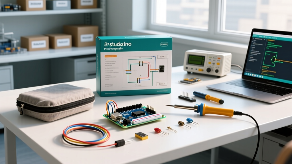

Why the Official Arduino Student Kit Remains the 2026 Standard
Whether you are a high school STEM educator, a university engineering student, or a self-taught maker, the official Arduino Student Kit (Model AKX00028) remains the most reliable entry point into embedded systems. While the market is flooded with generic clone kits, the official student kit provides guaranteed hardware compatibility, high-quality breadboards with reliable internal spring clips, and a structured curriculum that aligns with modern C++ standards used in the Arduino IDE 2.x ecosystem.
In this comprehensive tutorial, we will move past the basic 'blink' sketch and build a fully functional, multi-state traffic light controller. This project will teach you essential concepts including GPIO pin manipulation, current limiting via Ohm's Law, and sequential logic programming.
Component Audit: What You Are Actually Working With
Before writing code, it is critical to understand the exact specifications of your hardware. The official student kit centers around the Arduino UNO R3, featuring the ATmega328P microcontroller. Below is a breakdown of the core components we will use for this tutorial.
| Component | Quantity | Technical Specification | Primary Purpose |
|---|---|---|---|
| Arduino UNO R3 | 1 | ATmega328P, 5V logic, 16MHz clock | Main microcontroller and power source |
| Transparent Breadboard | 1 | 400 tie-points, 23-gauge wire max | Solderless circuit prototyping |
| 5mm LEDs (Red, Yellow, Green) | 9 | 2.0V - 2.2V forward voltage, 20mA max | Visual state indicators |
| Carbon Film Resistors | 70+ | 220Ω, 560Ω, 1kΩ, 10kΩ (1/4 Watt) | Current limiting and pull-down networks |
| USB Type-A to Type-B Cable | 1 | Shielded, 1 meter length | Serial communication and 5V power delivery |
Phase 1: Configuring the Arduino IDE for Your Board
The first step in any microcontroller project is establishing a reliable toolchain. As of 2026, the Arduino IDE 2.3.x is the recommended desktop environment, offering advanced features like auto-completion, real-time serial plotting, and integrated debugging for compatible boards.
- Download and Install: Navigate to the official Arduino software page and download the IDE for your operating system (Windows, macOS, or Linux).
- Board Selection: Connect your UNO R3 to your computer via the provided USB Type-B cable. Open the IDE, navigate to Tools > Board, and select Arduino UNO.
- Port Configuration: Go to Tools > Port. On Windows, this will appear as a COM port (e.g., COM3). On macOS and Linux, it will appear as a serial device (e.g., /dev/cu.usbmodem14101). If the port is greyed out, your cable may be a 'charge-only' cable lacking internal data lines—swap it immediately.
Phase 2: Wiring a Multi-State Traffic Light Circuit
We are going to wire three independent LEDs to simulate a traffic light. However, you cannot simply connect an LED directly between a 5V GPIO pin and Ground. Doing so will draw excessive current, potentially destroying the LED and permanently damaging the ATmega328P's internal silicon traces.
Applying Ohm's Law for Current Limiting
The ATmega328P GPIO pins can safely source a continuous current of 20mA per pin, with an absolute maximum rating of 40mA. A standard red 5mm LED has a forward voltage (Vf) of approximately 2.0V and a target current (I) of 20mA (0.02A). Using Ohm's Law (R = V / I), we calculate the required resistor:
Calculation: Supply Voltage (5V) - LED Forward Voltage (2.0V) = Voltage Drop across Resistor (3.0V).
R = 3.0V / 0.02A = 150Ω.
Expert Tip: Always round up to the nearest standard resistor value to provide a safety margin. The 220Ω resistors included in your Arduino student kit are perfect for this application, limiting current to a safe ~13.6mA.
Step-by-Step Wiring Instructions
- Step 1: Insert the short leg (cathode) of the Red, Yellow, and Green LEDs into the negative (blue) power rail of the breadboard.
- Step 2: Connect a jumper wire from the negative power rail to any GND (Ground) pin on the Arduino UNO.
- Step 3: Insert a 220Ω resistor inline with the long leg (anode) of each LED. Ensure the resistor bridges the center trench of the breadboard to prevent a short circuit.
- Step 4: Use male-to-male jumper wires to connect the Red LED to Digital Pin 8, the Yellow LED to Digital Pin 9, and the Green LED to Digital Pin 10.
Phase 3: Writing and Uploading the Sketch
With the hardware secured, we move to the software. The Arduino language is a simplified implementation of C++. We will use digitalWrite() to set the pins HIGH (5V) or LOW (0V), and delay() to pause the program execution.
// Traffic Light Controller Sketch
const int redPin = 8;
const int yellowPin = 9;
const int greenPin = 10;

void setup() {
  // Initialize digital pins as outputs
  pinMode(redPin, OUTPUT);
  pinMode(yellowPin, OUTPUT);
  pinMode(greenPin, OUTPUT);
}

void loop() {
  // Green Light Phase (10 seconds)
  digitalWrite(greenPin, HIGH);
  delay(10000);
  digitalWrite(greenPin, LOW);

  // Yellow Light Phase (3 seconds)
  digitalWrite(yellowPin, HIGH);
  delay(3000);
  digitalWrite(yellowPin, LOW);

  // Red Light Phase (10 seconds)
  digitalWrite(redPin, HIGH);
  delay(10000);
  digitalWrite(redPin, LOW);
}
Click the Upload button (the right-facing arrow in the top left corner). The IDE will compile the code, verify memory usage, and push the binary to the UNO's flash memory via the bootloader. Your traffic light will immediately begin its sequence.
Advanced Troubleshooting: Beyond the Basics
Even with a high-quality Arduino student kit, beginners frequently encounter hardware and software anomalies. Here is how to diagnose the most common failure modes, drawing on years of lab troubleshooting experience.
1. The 'avrdude: stk500_recv(): programmer is not responding' Error
This is the most notorious error in the Arduino ecosystem. It means the IDE cannot communicate with the bootloader on the ATmega16U2 USB-to-Serial chip.
- Fix A (Port Conflict): Disconnect any other USB devices, particularly 3D printers or other serial devices, which may be hijacking the COM port.
- Fix B (Bootloader Loop): Press and hold the physical 'RESET' button on the UNO. Click 'Upload' in the IDE. The moment the console says 'Sketch uses X bytes', release the RESET button. This forces the board into bootloader mode at the exact right millisecond.
2. The 'Ghost LED' or Dim Glow Issue
If an LED is faintly glowing when it should be completely off, you are likely experiencing 'floating pin' interference or a breadboard power rail continuity issue.
- The Breadboard Split: Most 400-point breadboards have a physical break in the middle of the long red and blue power rails (often indicated by a gap in the printed line). If your ground wire is plugged into the bottom half, but your LED cathode is in the top half, the circuit is open.
- Electromagnetic Interference (EMI): Ensure your jumper wires are not acting as antennas near high-frequency sources. Keep your wiring neat and use shorter jumper wires where possible.
Expanding Your Kit: Next Steps for 2026
Once you have mastered digital outputs and basic timing, the Arduino student kit offers extensive room for growth. The included potentiometer and photoresistor will allow you to explore analog inputs using the analogRead() function, mapping 0-5V signals to 10-bit integer values (0-1023). Furthermore, as you progress into IoT (Internet of Things) applications, consider upgrading your main board to the Arduino UNO R4 WiFi, which maintains the exact same physical footprint and pinout as your current R3, but adds a powerful Renesas RA4M1 32-bit Cortex-M4 processor and an ESP32-S3 for seamless wireless connectivity.
By treating your student kit not just as a toy, but as a professional prototyping sandbox, you will build the foundational electrical engineering skills required to design complex, real-world embedded systems.