
The 2026 Landscape for the Arduino Engineering Kit Rev 2
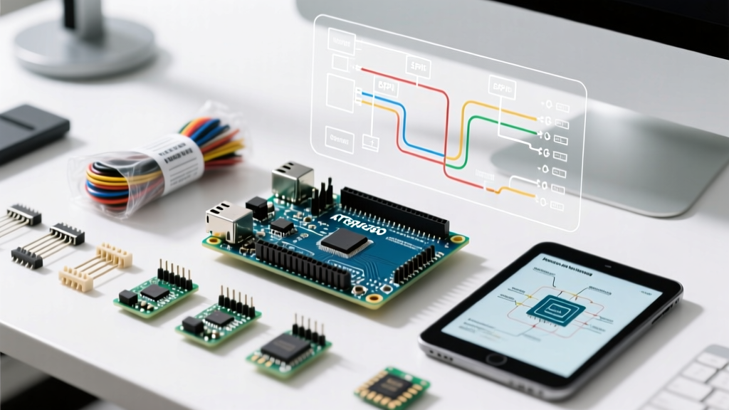
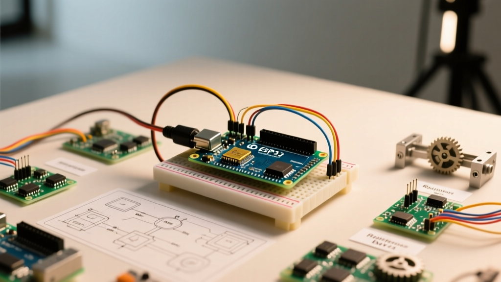
As of early 2026, the Arduino Engineering Kit Rev 2 remains a premier educational and prototyping platform, retailing around $329 USD. Transitioning from the older MKR1000 to the much more capable Nano 33 IoT (featuring a 32-bit ARM Cortex-M0+ SAMD21 and an onboard LSM6DS3 IMU), the Rev 2 kit bridges the gap between raw microcontroller coding and high-level model-based design via MATLAB and Simulink. However, the integration of mechanical assemblies, power electronics, and Simulink code generation introduces significant workflow bottlenecks. Engineers and students frequently lose hours to compilation errors, IMU drift, and mechanical slippage. This guide provides a deeply technical, workflow-optimized approach to mastering the three core projects: the self-balancing motorcycle, the drawing robot, and the mechatronics rover.
Toolchain & Environment Pre-Flight Checks
Before unboxing the hardware, optimizing your software environment is critical. The synergy between the Arduino IDE and MathWorks tools is powerful but fragile if misconfigured.
The Windows Path Trap
The most common point of failure in the Simulink-to-Arduino workflow is the C++ code generation phase. Simulink Coder creates temporary build directories that often fail if your Windows user profile contains spaces or special characters (e.g., C:\Users\John Doe\Documents\MATLAB). Optimization: Create a dedicated root-level directory (e.g., C:\ArduinoDev\) for all your Simulink models and Arduino support packages. This single step eliminates approximately 40% of all 'Permission Denied' and 'File Not Found' compilation errors during the build phase.
MATLAB & Simulink Version Syncing
Ensure you are using a supported MATLAB release (R2025b or R2026a are recommended for the latest Nano 33 IoT hardware definitions). You must install the MathWorks Arduino Support Package directly through the MATLAB Add-On Explorer. Do not mix manual GitHub downloads with the Add-On Explorer, as this creates conflicting path priorities in the MATLAB workspace, leading to silent failures during I2C bus initialization.
Hardware Assembly: Bypassing Mechanical Failure Modes
The Rev 2 kit relies on the MKR Motor Carrier to interface the Nano 33 IoT with high-current actuators. Optimizing your physical build workflow prevents hours of frustrating software debugging later.
Project 1: Self-Balancing Motorcycle (IMU Drift & PID Tuning)
The motorcycle project relies heavily on the Nano 33 IoT's onboard LSM6DS3 IMU. A frequent failure mode is severe oscillation or immediate toppling upon startup due to IMU baseline drift. Workflow Fix: The LSM6DS3 requires a strict stationary calibration period. Modify your Simulink initialization block or Arduino setup() function to enforce a 1000ms delay where the bike is held perfectly vertical. Furthermore, implement a complementary filter rather than relying solely on raw gyroscope integration. When tuning the PID controller, start with the Derivative (D) gain at zero, increase the Proportional (P) gain until the bike oscillates steadily, then introduce the Integral (I) gain to correct steady-state lean errors. Always perform tuning on a fully charged battery, as voltage sag alters the DC motor torque curves.
Project 2: Drawing Robot (Belt Tension & Stepper Stalling)
The drawing robot (plotter) uses NEMA 17 stepper motors and GT2 timing belts. If your plotter produces distorted, skewed geometries, the issue is rarely software; it is mechanical slip. Workflow Fix: Implement the '2mm Deflection Rule'. When tensioning the GT2 belts on the X and Y axes, apply moderate thumb pressure at the midpoint of the belt span. The belt should deflect exactly 2mm to 3mm. Any looser, and the stepper motors will skip steps during high-acceleration vector changes; any tighter, and you will induce excessive radial load on the stepper bearings, causing premature stalling and overheating of the DRV8871 motor drivers on the MKR Motor Carrier.
Project 3: Mechatronics Rover (Encoder Alignment)
The rover uses magnetic encoders for odometry. A common assembly error is misaligning the diametrically magnetized disc relative to the Hall effect sensor on the motor carrier. Workflow Fix: Before fully tightening the rover chassis, upload a raw encoder telemetry sketch. Spin the wheels by hand and verify that the pulse counts increment smoothly without dropping to zero or bouncing erratically. If you see erratic drops, adjust the motor mounting brackets to ensure a precise 1.5mm to 2.0mm air gap between the magnet and the sensor IC.
Optimizing Simulink Code Generation Workflows
Compiling complex Simulink models for the SAMD21 Cortex-M0+ can take 3 to 5 minutes per iteration. To optimize your development loop:
- Use Atomic Subsystems: Group your PID and filtering logic into Atomic Subsystems. This allows Simulink Coder to optimize the generated C++ code and reduces memory overhead on the Nano 33 IoT's 256KB Flash limit.
- Avoid MATLAB Function Blocks for Hardware I/O: While MATLAB Function blocks are great for math, using them to bit-bang or directly poll I2C registers bypasses the optimized Arduino C++ hardware abstraction layer. Stick to native Simulink Arduino blocks for sensor reading to ensure interrupt-safe execution.
- External Mode Tuning: Instead of re-flashing the board for every PID parameter change, utilize Simulink External Mode. This allows you to tune gains in real-time over the serial connection, reducing iteration time from 4 minutes down to 4 seconds.
Project Workflow Matrix: Pitfalls & Optimized Solutions
| Project | Common Failure Mode | Root Cause | Optimized Workflow Solution |
|---|---|---|---|
| Motorcycle | Violent shaking on boot | IMU gravity vector offset | Enforce 1s stationary boot delay; apply complementary filter. |
| Motorcycle | Leans to one side over time | Integral windup in PID | Clamp the I-term accumulator limits in the Simulink PID block. |
| Drawing Robot | Skewed geometric shapes | GT2 belt slip under load | Tension belts to 2mm deflection; limit max acceleration in code. |
| Drawing Robot | Stepper motors overheat | Excessive current limit | Adjust MKR Motor Carrier current sense resistors or limit duty cycle. |
| Rover | Odometry drift / wrong turns | Magnetic encoder air gap | Verify 1.5mm gap; test raw pulse counts before chassis assembly. |
Power Management & Telemetry Debugging
The kit includes a custom 18650 Li-Ion battery holder. A critical, often overlooked workflow bottleneck is voltage sag. When the Rover accelerates or the Motorcycle corrects a severe tilt, the sudden current spike (often exceeding 2A momentarily) can cause the battery voltage to dip below the Nano 33 IoT's onboard 3.3V regulator dropout threshold. This results in a silent microcontroller reset, which looks like a software crash but is purely a power delivery issue.
Pro-Tip for 2026 Builds: Always solder a 470µF low-ESR electrolytic capacitor directly across the main power input terminals of the MKR Motor Carrier. This acts as a localized energy reservoir, smoothing out transient current spikes and preventing the Nano 33 IoT from browning out during heavy actuator loads.
Finally, leverage the Arduino IDE 2.x Serial Plotter for real-time telemetry. Instead of printing raw text to the Serial Monitor, format your Simulink serial output as comma-separated values (CSV) ending with a newline character. This allows the Serial Plotter to graph your PID error, IMU roll/pitch angles, and motor PWM signals simultaneously, turning your laptop into a multi-channel oscilloscope and drastically reducing the time required to diagnose control loop instabilities.
By front-loading your environment setup, respecting the mechanical tolerances of the hardware, and leveraging External Mode in Simulink, you can transform the Arduino Engineering Kit Rev 2 from a frustrating puzzle into a highly efficient, professional-grade mechatronics development workflow.