
The Logic Level Bottleneck: 3.3V vs 5V Microcontrollers
When building an Arduino LED controller for addressable strips or matrices, the most common point of failure is not the code—it is the physical logic level mismatch between the microcontroller and the LED driver chip. Understanding voltage thresholds is critical for stable operation.
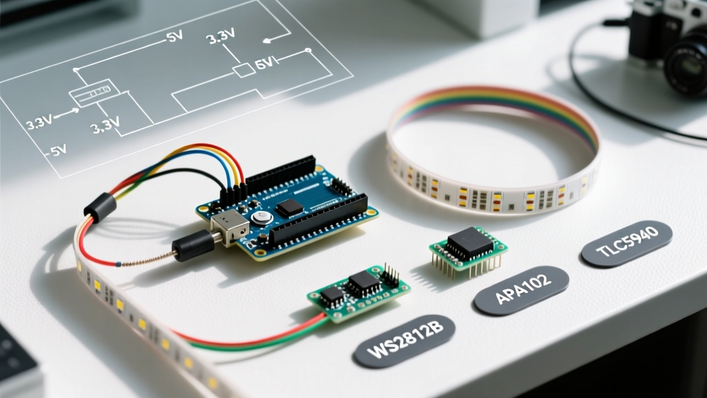
The ubiquitous WS2812B (often branded as NeoPixel) requires a logic HIGH signal of at least 0.7 × VDD. If you are powering the strip at 5V, the data pin must receive a minimum of 3.5V to register a '1'. Classic 5V boards like the Arduino Uno R3 or Nano output 5V, making them natively compatible. However, modern 3.3V boards like the Arduino Nano 33 IoT, Zero, or the widely used ESP32 output only 3.3V. Connecting a 3.3V MCU directly to a 5V WS2812B strip results in erratic flickering, random color bursts, or complete failure.
The Fix: Do not rely on software workarounds for hardware voltage deficits. Use a dedicated high-speed level shifter like the Texas Instruments 74AHCT125. Costing roughly $0.60, this IC safely translates 3.3V logic to 5V without introducing the timing delays inherent in MOSFET-based bi-directional shifters.
Protocol and Driver Chip Compatibility Matrix
Not all addressable LEDs communicate using the same protocol. Your choice of Arduino board must align with the LED's data requirements. Below is a compatibility matrix detailing the most common LED driver chips used in maker projects.
| LED Chipset | Protocol | Logic Tolerance | Max Refresh / Clock | Best MCU Match |
|---|---|---|---|---|
| WS2812B | Single-wire NRZ | Strict 5V (0.7x VDD) | ~800 Hz (Timing critical) | Arduino Uno R3, Nano Every |
| APA102 (DotStar) | SPI (Clock + Data) | Forgiving 3.3V / 5V | Up to 20 MHz Clock | ESP32-S3, Teensy 4.1 |
| SK6812 | Single-wire NRZ | Strict 5V (0.7x VDD) | ~800 Hz (Timing critical) | Arduino Uno R4 Minima |
| TLC5940 | Serial (SIN/SCLK) | 5V Preferred | 30 MHz SCLK | Arduino Mega 2560 |
| PCA9685 | I2C | 3.3V / 5V Compatible | 400 kHz I2C Bus | Any I2C-capable MCU |
Why APA102 is Superior for High-Speed Applications
If your project involves persistence-of-vision (POV) displays or high-frame-rate video mapping, the WS2812B's strict timing interrupts will bottleneck your Arduino. The APA102 utilizes a standard SPI protocol. According to Arduino's official SPI documentation, hardware SPI can push data at 8MHz or higher, completely bypassing the microsecond-level timing loops required by single-wire LEDs. This frees up the MCU's CPU cycles for complex math or wireless communication.
SRAM Limits and Board Selection for Large Matrices
Memory allocation is the silent killer of large-scale LED installations. Every WS2812B or SK6812 pixel requires 3 bytes of SRAM (Red, Green, Blue) in the microcontroller's memory buffer. If you are using an RGBW strip (like the SK6812 RGBW), that requirement jumps to 4 bytes per pixel.
- Arduino Uno R3 (ATmega328P): 2KB SRAM. Maximum safe limit is roughly 500 LEDs (1500 bytes), leaving minimal room for the stack and other variables.
- Arduino Nano Every (ATmega4809): 6KB SRAM. Can comfortably drive up to 1,200 LEDs.
- ESP32-S3: 512KB SRAM (plus external PSRAM options). Capable of driving tens of thousands of pixels, making it the undisputed king for large architectural matrices.
- Teensy 4.1: 1MB SRAM. Features dedicated FlexIO pins and DMA (Direct Memory Access) to push LED data without CPU intervention.
For matrices larger than 32x32 (1024 pixels), abandon 8-bit AVR boards entirely. The memory overhead of the CRGB array will cause stack collisions and random reboots.
Power Injection and Grounding Physics
A common misconception is that an Arduino LED controller setup only requires data and a single power feed. Addressable LEDs draw massive current. A single WS2812B pixel drawing full white (R+G+B) consumes approximately 60mA. A strip of 100 pixels will pull 6 Amps. The thin copper traces on standard LED strips (usually 18-20 AWG equivalent) cannot carry this current over long distances without severe voltage drop.
The 50-Pixel Injection Rule
To prevent the 'yellowing' effect at the end of a strip (where blue LEDs, requiring the highest forward voltage, starve first), you must inject power and ground every 50 pixels (approximately 3 meters of 30-LED/m strip).
- Use 18 AWG silicone wire for power injection runs up to 2 meters from the power supply.
- Drop to 20 AWG for short jumper wires directly to the strip's copper pads.
- Always connect the ground (GND) of your power supply to the GND of your Arduino. Without a common ground reference, the data signal will float, causing chaotic LED behavior.
- Place a 1000µF to 2200µF electrolytic capacitor (rated for at least 10V) across the 5V and GND terminals at the power injection point to smooth out transient current spikes when the strip turns on.
Software Library Ecosystem: FastLED vs. Adafruit NeoPixel
Hardware compatibility is only half the battle; your software library must support the specific chipset and board architecture. The two dominant libraries in the ecosystem offer different trade-offs.
The Adafruit NeoPixel Überguide remains the gold standard for beginners. It is lightweight, easy to implement, and supports basic color manipulation. However, it disables interrupts while pushing data to single-wire LEDs, which can break software serial, IR receivers, and certain Wi-Fi functions on ESP boards.
FastLED is the professional's choice. It utilizes hardware-specific optimizations (like DMA on ESP32 and SAMD boards) to push data in the background, keeping interrupts enabled. FastLED also includes advanced color math, dithering, and palette management. If you are building an ESP32-based LED controller for a 2026 smart home installation, FastLED's non-blocking architecture is mandatory.
Troubleshooting Edge Cases and Failure Modes
Even with perfect wiring, environmental and electrical noise can disrupt your Arduino LED controller. Use this diagnostic checklist for common edge cases:
- The 'First Pixel Glitch': If the first LED in the strip shows random colors but the rest are fine, the data signal is degrading over the initial wire run. Solder a 300-ohm to 500-ohm resistor directly to the data pad of the first LED to terminate signal reflections.
- Wi-Fi Interference (ESP32): When using an ESP32 with WS2812B strips, enabling Wi-Fi can cause strip flickering due to interrupt clashes. Solution: Use the ESP32's RMT (Remote Control Transceiver) peripheral via the FastLED library, which handles LED timing in dedicated hardware, completely isolated from Wi-Fi interrupts.
- Power Supply Over-Voltage: Cheap 5V switching power supplies can sometimes output 5.3V to 5.5V under light loads. While the LEDs will tolerate this, it pushes the 0.7 × VDD logic threshold higher, making 5V logic from an Arduino Uno marginal. Always verify PSU output with a multimeter under a loaded state.
By matching the correct logic levels, respecting SRAM boundaries, and implementing rigorous power injection standards, your Arduino LED controller will transition from a fragile prototype to a robust, permanent installation.