
The Reality of DMX512 Over RS485
Building a custom lighting controller using an Arduino DMX shield is a rite of passage for DIY stage technicians and installation artists. Whether you are using a premium Conceptinetics DMX Shield (typically $45-$60) or a generic Chinese MAX485 TTL-to-RS485 module ($2-$4), the underlying protocol remains the same: DMX512 is essentially RS485 running at a blistering 250 kbaud. However, this high-speed differential signaling is notoriously unforgiving of poor wiring, bus contention, and software misconfigurations.
According to the DMX512 Technical Reference, the protocol requires strict adherence to electrical timing and physical layer topologies. When your Arduino fails to upload code, or your moving heads start ghosting mid-show, the root cause is almost always a collision between the ATmega328P's hardware limitations and the RS485 physical layer. This guide provides deep-level error diagnosis for the most critical Arduino DMX shield failures.
Error 1: The Serial Port Collision (Upload Failures)
The Symptom
You press "Upload" in the Arduino IDE, the TX/RX LEDs flicker erratically, and the console throws an avrdude: stk500_recv(): programmer is not responding error. The sketch worked yesterday, but today the board is bricked.
The Root Cause: Bus Contention on D0/D1
Most entry-level Arduino DMX shields hardwire the MAX485 transceiver’s Receiver Output (RO) and Driver Input (DI) pins directly to the Arduino’s Hardware Serial pins (D0 and D1). During a sketch upload, the onboard ATmega16U2 USB-to-Serial chip attempts to drive D0 and D1 with the new hex file. If the DMX shield is actively holding the bus in a transmit or receive state, a bus contention occurs. The USB chip cannot overpower the MAX485 chip, resulting in corrupted bootloader handshakes.
The Diagnostic Fix
- Hardware Switch: Premium shields include a physical DPDT toggle switch labeled "UART/USB" and "DMX". You must flip this to USB before uploading, and back to DMX before powering the lighting rig.
- SoftwareSerial Migration: If your shield lacks a switch, desolder the D0/D1 header pins and jumper the MAX485 RO/DI pins to D8 and D9. You will need to swap your library from hardware serial to
AltSoftSerialorSoftwareSerial. Note that standardSoftwareSerialstruggles at 250 kbaud;AltSoftSerialis mandatory for reliable DMX transmission on alternative pins.
Error 2: Signal Dropouts and "Ghost" Channels
The Symptom
Your DMX fixtures work perfectly on a 3-foot workbench. Once you run 150 feet of cable to the stage, fixtures flicker, strobe randomly, or ignore channel updates entirely.
The Root Cause: Capacitance and Missing Termination
DMX512 operates at 250,000 bits per second. At this frequency, the physical cable acts as a capacitor. Standard XLR-3 microphone cables possess a capacitance of roughly 100pF per foot. Over long runs, this capacitance forms a low-pass filter that rounds off the sharp square-wave edges of the RS485 signal, causing the receiver’s UART to misinterpret bit boundaries.
Furthermore, the Texas Instruments RS-485 Design Guide explicitly warns about signal reflection on unterminated transmission lines. Without a termination resistor, the high-speed signal bounces off the end of the cable, colliding with incoming data packets.
The Diagnostic Fix
- Upgrade to True DMX Cable: Replace mic cables with AES/EBU or dedicated DMX cables (e.g., Belden 9841), which feature 110-120Ω impedance and low capacitance (~40pF/ft). A 100-foot roll of true DMX cable costs around $120-$150, but it is non-negotiable for stable 250 kbaud transmission.
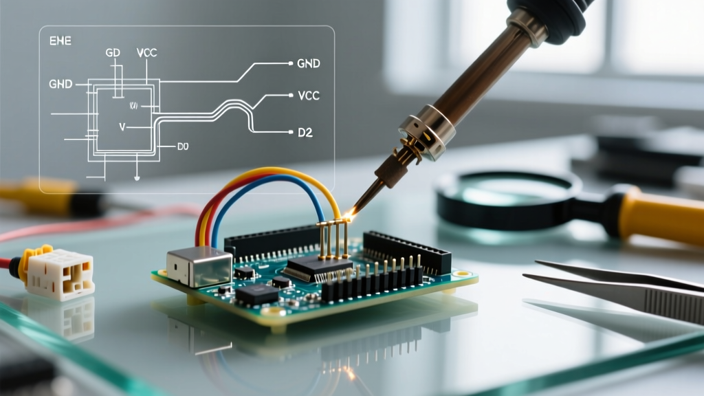
- Install the 120Ω Termination Resistor: Solder a 120-ohm, 1/4-watt resistor across the Data+ (Pin 3) and Data- (Pin 2) terminals of the very last fixture in your daisy chain. Many modern LED pars have a built-in DIP switch for this; if not, you must build a custom XLR terminator plug.
- Implement Fail-Safe Biasing: If your Arduino DMX shield reboots or loses power, the RS485 lines float, causing fixtures to interpret noise as valid DMX data (resulting in random flashing). Add a 560Ω pull-up resistor from Data+ to VCC (5V) and a 560Ω pull-down resistor from Data- to GND at the Arduino shield output.
Error 3: Addressing Off-By-One and Universe Boundaries
The Symptom
You set your moving head to DMX Address 001. In your Arduino sketch, you write DmxMaster.write(1, 255);, but the fixture does nothing. Writing to channel 2 triggers the fixture.
The Root Cause: Library Indexing Quirks and Break Timing
The DMX512 standard specifies channels 1 through 512. However, C++ arrays are zero-indexed (0-511). Different Arduino DMX libraries handle this translation differently, leading to massive confusion during error diagnosis. Additionally, DMX requires a minimum 88μs "Break" signal to reset the universe. Because the ATmega328P hardware UART lacks native break generation, libraries like DMXSerial hack this by temporarily dropping the baud rate to 90kbaud to send a 0x00 byte, then switching back to 250kbaud. On cheap Arduino clones with inaccurate ceramic resonators instead of quartz crystals, this timing hack fails, causing fixtures to ignore the entire universe.
Expert Tip: Always check your specific library’s source code for the channel offset. The Conceptinetics library uses 1-based indexing (1-512) for its public API, while raw byte buffers in custom implementations often require a 0-based index. If using a clone board, ensure it has a 16.000 MHz quartz crystal to support the baud-rate switching hack.
Diagnostic Matrix: Quick Reference Guide
| Symptom | Probable Root Cause | Hardware / Software Fix |
|---|---|---|
| avrdude upload timeout | MAX485 bus contention on D0/D1 | Toggle shield to USB mode; use AltSoftSerial |
| Flickering on long cable runs | High cable capacitance / reflections | Use 120Ω DMX cable; add 120Ω termination |
| Fixtures flash randomly on boot | Floating RS485 lines (no bias) | Add 560Ω pull-up/pull-down bias resistors |
| Channel 1 doesn't respond | Zero-index vs One-index library mismatch | Shift software array index by +1 or -1 |
| Arduino resets when DMX connects | Ground loop / voltage spike | Install ADuM140x digital isolator on shield |
Advanced Protection: Surviving the Stage Environment
The most catastrophic Arduino DMX shield error is not a software bug; it is a fried ATmega328P microcontroller. Stage environments are electrically hostile. If a lighting fixture develops a ground fault, or if an XLR cable is accidentally patched into an analog audio snake carrying 48V phantom power, lethal voltage can travel back through the RS485 Data lines and straight into your Arduino’s I/O pins.
To prevent catastrophic hardware failure, professional DIY DMX shields incorporate galvanic isolation. If you are building a custom shield using a bare MAX485 chip, integrate an ADuM1401 or IL300 optoisolator between the Arduino’s TX/RX pins and the MAX485 logic pins. This breaks the electrical continuity while allowing the 250 kbaud data to pass via magnetic or optical coupling. While this adds roughly $3-$5 to your BOM (Bill of Materials), it saves your $25 Arduino board from being destroyed by a $2,000 moving head fixture with a faulty power supply.
Final Verification Steps
Before deploying your Arduino DMX controller to a live venue, run a 24-hour burn-in test using a DMX terminator and a single test fixture. Monitor the RS485 Data+ and Data- lines with an oscilloscope using a differential probe. You should see crisp, flat-topped square waves with minimal ringing on the edges, and a differential voltage swing between +5V and -5V. If the waveforms look like rounded shark fins, your cable capacitance is too high. Furthermore, use a multimeter to measure the AC/DC voltage between the Arduino GND and the XLR Pin 1 (Shield/Ground) before plugging in the data lines; the RS485 common-mode voltage range is strictly -7V to +12V. If the ground potential difference exceeds this, the MAX485 chip will latch up or burn out. Mastering these physical layer diagnostics is what separates a fragile workbench prototype from a road-ready lighting controller.