
Why You Need a Dedicated Arduino Diagram Maker
Transitioning from a messy breadboard prototype to a permanent perfboard or custom PCB is a rite of passage for every maker. However, relying on hand-drawn sketches or mental maps inevitably leads to floating pins, missing decoupling capacitors, and fried microcontrollers. Using a dedicated Arduino diagram maker bridges the gap between a temporary breadboard circuit and a manufacturable schematic. In 2026, the ecosystem for MCU diagramming has matured significantly, offering tools that range from beginner-friendly visual simulators to professional-grade EDA (Electronic Design Automation) suites.
This tutorial will walk you through the top diagramming platforms, how to structure your schematics for ATmega328P and ESP32-based projects, and the critical edge cases that separate amateur wiring diagrams from professional engineering schematics.
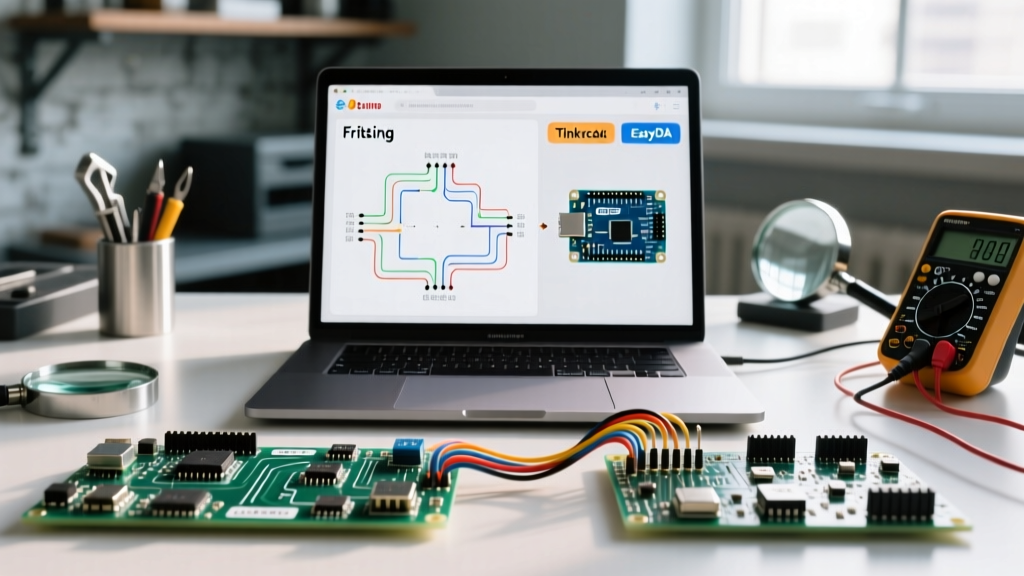
Comparing the Top Arduino Diagram Makers
Choosing the right software depends on your end goal: visual documentation, code simulation, or PCB fabrication. Below is a comparison matrix of the industry-standard tools used by makers and engineers today.
| Tool | Cost (2026) | Simulation Engine | PCB Export | Best Use Case |
|---|---|---|---|---|
| Tinkercad Circuits | Free | SPICE-based | No | Beginners, visual learning, basic code testing |
| Fritzing | $8.00 (One-time) | No | Yes (Gerber) | Visual breadboard documentation, maker tutorials |
| EasyEDA (Standard) | Free / $99/yr Pro | ngspice | Yes (Advanced) | Professional PCB design, complex MCU routing |
| Wokwi | Free / $9/mo Club | Custom (ESP/STM32) | No | IoT firmware simulation, WiFi/Bluetooth testing |
Tutorial 1: Visual Documentation with Fritzing
Fritzing remains the undisputed king of visual breadboard layouts. If you are writing a tutorial, publishing a blog post, or creating a wiring guide for a team, Fritzing's 'Breadboard View' is the industry standard. You can download it directly from Fritzing Official.
Step-by-Step: Creating a Breadboard Diagram
- Initialize the Board: Drag the 'Arduino Uno R3' or 'Nano' from the core library. Note that Fritzing accurately models the ATmega16U2 USB-to-Serial chip and the ATmega328P-PU main MCU.
- Component Placement: Add your sensors. For an I2C OLED display (SSD1306), place it on the rails. Use the color-coding standard: Red for 5V/VCC, Black for GND, Yellow for SDA, and Orange for SCL.
- Wire Routing: Click and drag to create wires. Use the 'bend point' feature (clicking on the wire and dragging) to route cables neatly around components, avoiding visual clutter.
- Switch to Schematic View: Press the 'Schematic' tab. Fritzing will automatically translate your physical breadboard layout into standard IEEE logic symbols. You will need to manually rearrange the components to ensure signal lines flow logically from left to right.
Pro-Tip: Fritzing's auto-router for PCB traces is notoriously poor for high-speed buses. If you plan to export to Gerber files for manufacturing, always route I2C, SPI, and UART traces manually, keeping them as short and parallel as possible to avoid crosstalk.
Tutorial 2: Simulation and Testing with Tinkercad
Before you commit to soldering, simulating your circuit can save you from releasing the 'magic smoke'. Tinkercad Circuits is a browser-based Arduino diagram maker that includes a real-time AVR simulation engine.
Building a Standalone ATmega328P Circuit
Simulating a standalone chip is where Tinkercad shines, but it requires strict adherence to hardware rules that beginners often miss.
- The Decoupling Capacitor: You must place a 100nF (0.1µF) ceramic capacitor across the VCC (Pin 7) and GND (Pin 8) pins of the ATmega328P. Without this, the simulation (and real life) will suffer from brownout resets due to voltage sag during logic switching.
- The Crystal Oscillator: Drag a 16MHz resonator or crystal with built-in 22pF load capacitors to Pins 9 (XTAL1) and 10 (XTAL2). If you use a raw quartz crystal, you must manually add two 22pF ceramic capacitors from each crystal leg to GND.
- Reset Pin Protection: Tie Pin 1 (RESET) to VCC via a 10kΩ pull-up resistor. In Tinkercad, failing to do this will leave the pin floating, causing the simulated MCU to continuously reboot.
Once wired, click 'Start Simulation' and upload your Arduino C++ code. Tinkercad's serial monitor will accurately reflect baud-rate timing and I2C bus errors.
Tutorial 3: Professional Schematics with EasyEDA
When your project moves beyond a simple sensor breakout and requires a custom 2-layer or 4-layer PCB, you need a true EDA tool. EasyEDA is the go-to choice in 2026, primarily due to its seamless integration with the LCSC component library and JLCPCB manufacturing.
Schematic Capture Best Practices
Unlike Fritzing, EasyEDA does not have a 'breadboard' view. You work directly with abstract schematic symbols. Here is how to structure a professional MCU schematic:
- Modular Design: Do not draw one massive schematic. Use hierarchical blocks. Create separate sheets for the 'MCU Core', 'Power Supply (LDO/Buck)', 'Motor Drivers', and 'Sensor Interfaces'.
- Power Flags: Use explicit power flags (e.g.,
+5V,+3V3,GND) rather than routing physical wires across the entire page. This drastically reduces visual noise. - Decoupling Strategy: Place a 100nF X7R capacitor on every single VCC pin of the microcontroller. For an ATmega328P-AU (TQFP-32 package), this means placing capacitors on both digital VCC pins and the AVCC (Analog VCC) pin. Group them logically in the schematic, but remember that in the PCB layout phase, they must be placed physically adjacent to their respective pins.
Critical Edge Cases and Common Wiring Failures
Even the best Arduino diagram maker cannot prevent logical engineering errors. When reviewing your schematics, audit them against this checklist of common MCU failure modes:
1. Missing I2C Pull-Up Resistors
The I2C protocol uses open-drain outputs. The MCU and sensors can pull the SDA and SCL lines LOW, but they cannot drive them HIGH. You must include 4.7kΩ pull-up resistors tied to the logic voltage (3.3V or 5V). If you are connecting multiple I2C devices, the parallel resistance drops; ensure your total pull-up resistance does not fall below 2kΩ, or the MCU's internal sink transistors will overheat.
2. The Auto-Reset Circuit (DTR Line)
If you are designing a custom board with a USB-to-Serial chip (like the CH340 or CP2102), you need the auto-reset circuit to allow the Arduino IDE to upload code without pressing the physical reset button. Route a 100nF capacitor in series between the DTR pin of the USB chip and the RESET pin of the ATmega328P. Add a 1N4148 switching diode with the cathode pointing to the RESET pin and the anode to GND to protect against high-voltage spikes during ISP programming.
3. Logic Level Translation
A frequent mistake in 2026 maker projects is mixing 5V Arduino Unos with 3.3V sensors (like the BME280 or modern ESP-12F modules). Feeding 5V into a 3.3V I2C data line will degrade the silicon over time. Use a dedicated bidirectional logic level converter (like the TI TXS0108E or a simple BSS138 MOSFET-based module) in your diagram to isolate the voltage domains.
Exporting and Manufacturing Your Design
Once your schematic is flawless, the final step is translating it into physical hardware. If you used EasyEDA, generating the manufacturing files is a one-click process.
- Gerber Files: These define the copper traces, silkscreen, and solder mask layers. Ensure you select the 'Extended Gerber (RS-274X)' format.
- Drill Files: Excellon format is the standard. Verify that your plated through-holes (PTH) for headers and non-plated holes (NPTH) for mounting screws are correctly separated.
- BOM and CPL: If you are using PCBA (PCB Assembly) services, export the Bill of Materials (BOM) and Component Placement List (CPL). Double-check that all LCSC part numbers match the exact footprint on your board (e.g., ensuring you selected a 0603 footprint resistor, not a 0805).
Final Thoughts
Mastering an Arduino diagram maker is about more than just drawing lines between pins; it is about understanding the electrical realities of microcontrollers. Whether you are using Tinkercad to simulate a basic LED blink, Fritzing to document a workshop tutorial, or EasyEDA to design a commercial IoT node, adhering to strict schematic standards will save you hours of debugging and ensure your hardware survives the transition from the workbench to the real world.