
The Hardware Reality: Choosing the Right MicroSD Breakout
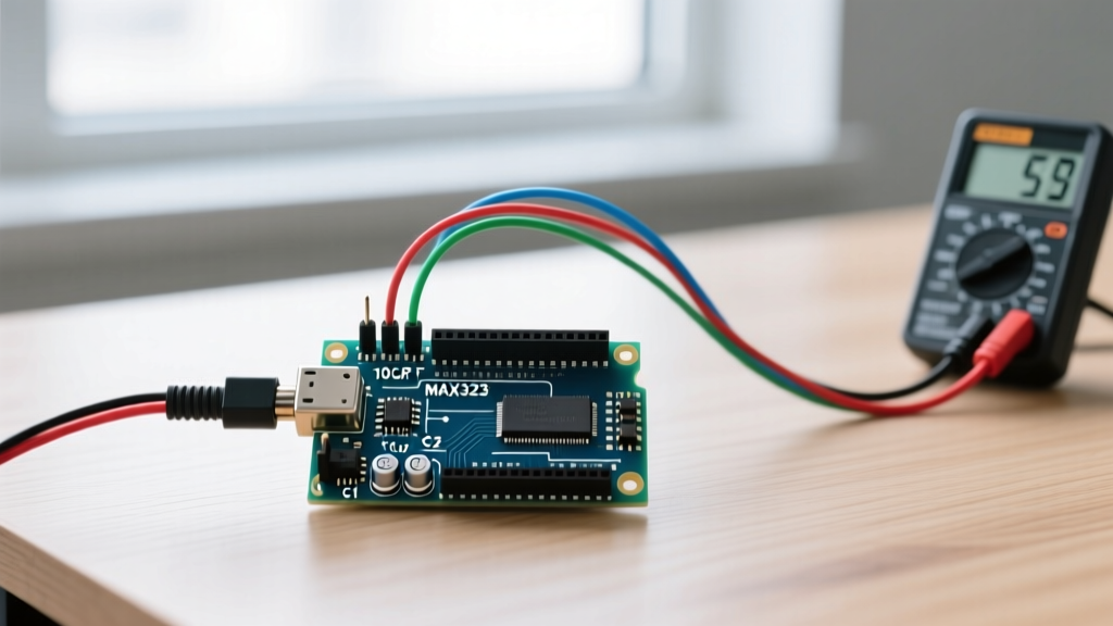
Configuring an Arduino and SD card interface is a rite of passage for data logging, environmental monitoring, and GPS tracking projects. However, what appears to be a simple SPI connection often devolves into silent data corruption, bus lockups, and mysterious microcontroller resets. The root cause almost always traces back to hardware selection and power delivery mismatches.
When sourcing a microSD breakout module, makers typically choose between ultra-cheap generic modules and premium engineered boards. As of 2026, a reliable 32GB SanDisk Ultra microSDHC card costs around $8.50, but pairing it with a $1.20 generic breakout board is a false economy.
| Module Type | Approx. Cost | Level Shifting | MISO Tri-State | Verdict |
|---|---|---|---|---|
| Generic 'Catalex' (Red/Green) | $1.20 - $1.80 | Resistor divider (Flawed) | No (Bus locking risk) | Avoid for 5V MCUs |
| LC Technology (ICSP Header) | $2.50 - $3.50 | None (3.3V only) | Yes | Good for 3.3V ESP32/RP2040 |
| Adafruit MicroSD Breakout | $7.50 | Dedicated IC (74AHCT125) | Yes | Best for 5V Arduino UNO/Mega |
The MISO Tri-State Failure Mode
The most insidious flaw in generic microSD modules is the lack of a tri-state buffer on the MISO (Master In Slave Out) line. On a proper SPI bus, when a device's Chip Select (CS) pin is HIGH, its MISO pin must enter a high-impedance (Hi-Z) state. Generic modules often wire the SD card's MISO directly to the header. If you share the SPI bus with another peripheral (like an NRF24L01 radio or a TFT display), the SD card will 'talk over' the other device, causing total bus corruption. Premium modules like the Adafruit 254 use a level-shifting IC that inherently handles tri-state logic correctly.
Wiring the SPI Bus: Pinouts and the 3.3V Logic Trap
SD cards operate strictly at 3.3V logic and require a 3.3V power supply. Feeding 5V into the VCC pin of a raw SD card will permanently destroy the silicon. Furthermore, feeding 5V logic signals (MOSI, SCK, CS) into a 3.3V SD card input pin will degrade the card's internal controller over time.
Standard Arduino SPI Pin Mapping
- Arduino UNO / Nano (ATmega328P): MOSI = Pin 11, MISO = Pin 12, SCK = Pin 13, CS = Pin 10 (or any digital pin, defined in software).
- Arduino Mega2560: MOSI = Pin 51, MISO = Pin 50, SCK = Pin 52, CS = Pin 53.
- ESP32 (Standard VSPI): MOSI = GPIO 23, MISO = GPIO 19, SCK = GPIO 18, CS = GPIO 5.
CRITICAL WARNING: If you are using a 5V Arduino (UNO/Mega), you must use a breakout board with active level shifters. Resistor voltage dividers on generic boards often fail to switch fast enough at standard SPI clock speeds (4MHz - 8MHz), resulting in CRC check failures and 'card.init failed' errors in your serial monitor.
Power Delivery: The Hidden 200mA Bottleneck
A frequent point of failure in Arduino and SD card configurations is power brownouts. During a sector write operation, an SD card's internal controller and NAND flash can draw transient current spikes up to 200mA.
Most cheap Arduino UNO clones utilize an AMS1117-3.3 linear voltage regulator to provide the 3.3V output pin. This regulator is typically rated for 800mA, but without adequate heatsinking and input capacitance, it will thermally throttle or drop voltage when subjected to the 200mA transient spikes from the SD card. This causes the Arduino's brownout detection (BOD) to trigger, resetting the microcontroller mid-write and corrupting the FAT32 file allocation table.
The Capacitor Fix
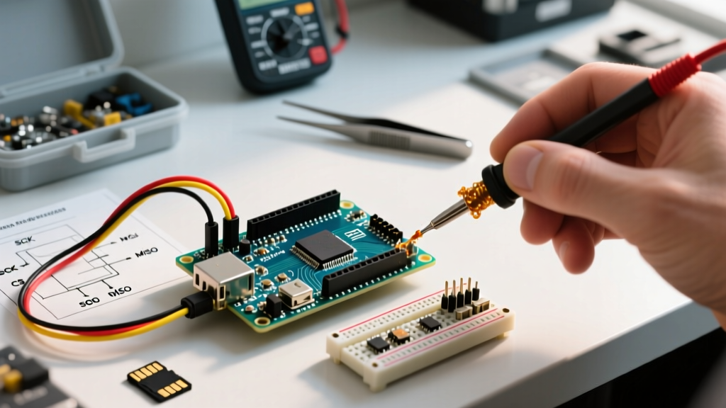
To stabilize the power rail, solder a decoupling capacitor network directly across the VCC and GND pins on the microSD breakout board header:
- Add a 100µF electrolytic capacitor to supply bulk charge during write bursts.
- Add a 0.1µF ceramic capacitor in parallel to filter high-frequency SPI switching noise.
Card Preparation: Why Windows Fails and SD Association Succeeds
MicroSD cards larger than 32GB (SDXC) are natively formatted as exFAT. The standard Arduino SD.h library only supports FAT16 and FAT32. Furthermore, formatting a card using the native Windows or macOS right-click 'Format' option often results in non-standard cluster sizes and hidden partition maps that the Arduino's lightweight FAT parser cannot read.
The Correct Formatting Workflow
You must use the official SD Memory Card Formatter provided by the SD Association. This tool bypasses the OS's logical volume manager and writes directly to the master boot record (MBR) according to strict SD specifications.
- Download and install the SD Memory Card Formatter (available for Win/Mac).
- Insert your microSD card (use a high-quality USB 3.0 adapter, not a built-in laptop slot which often misreports geometry).
- Select Overwrite Format (not Quick Format) to map out any bad NAND blocks.
- Ensure the Format Type is set to FAT32 (for cards 32GB and under) or use the
SdFatlibrary if you require exFAT for 64GB+ cards.
Software Configuration: Migrating to SdFat
The default SD.h library included in the Arduino IDE is a wrapper around an ancient version of the SdFat library. It consumes roughly 10-15% of an ATmega328P's 2KB SRAM just to initialize, and it lacks support for SPI transactions, which causes conflicts with modern interrupt-driven libraries.
For professional data logging, bypass SD.h entirely and install Bill Greiman's SdFat library via the Arduino Library Manager.
Optimal SdFat Initialization Parameters
When initializing the card, you must configure the SPI speed and Chip Select behavior. Here is the optimal configuration block for a 5V Arduino UNO using a level-shifted breakout:
#include 'SdFat.h'

// Use SdFs for FAT16/FAT32/exFAT support
SdFs sd;

void setup() {
  Serial.begin(115200);

  // Dedicate the SPI bus to the SD card to prevent conflicts
  if (!sd.begin(SdSpiConfig(10, DEDICATED_SPI, SD_SCK_MHZ(8)))) {
    Serial.println('SD initialization failed!');
    sd.initErrorHalt(&Serial);
  }
  Serial.println('SD card initialized successfully.');
}
Setting the configuration to DEDICATED_SPI allows the library to hold the CS line LOW across multiple block reads/writes, increasing throughput by up to 400% compared to shared SPI mode.
Advanced Troubleshooting Matrix
When your Arduino and SD card setup fails, the serial monitor rarely gives you a precise hardware diagnosis. Use this matrix to isolate the failure mode based on physical symptoms.
| Symptom | Root Cause | Actionable Fix |
|---|---|---|
card.init fails with error code 0x01 |
CS pin floating or wired to wrong GPIO. | Verify CS wiring. Ensure CS is pulled HIGH via 10kΩ resistor during boot. |
| Works on USB power, resets on battery | Voltage sag during 200mA write burst. | Add 100µF bulk capacitor. Upgrade to a switching buck converter (e.g., LM2596). |
| 'Volume initialization failed' (Error 0x02) | Invalid FAT32 format or hidden partition. | Reformat using SD Association Formatter with Overwrite option. |
| Corrupted CSV data (missing bytes) | Buffer overflow / slow SPI clock. | Implement a RAM buffer (e.g., 512 bytes) and write in full sectors. |
| Secondary SPI device (e.g., TFT) fails | SD MISO not tri-stating when CS is HIGH. | Replace generic SD module with Adafruit 254 or add 74AHCT125 buffer. |
Final Best Practices for 2026
Always implement a software buffer in your Arduino sketch. Writing single characters or short strings via file.print() forces the SD card to perform a read-modify-write cycle on the entire 512-byte sector, destroying write speeds and wearing out the NAND flash prematurely. Buffer your sensor data in a char array and push it to the card only when the buffer reaches 512 bytes, or use the SdFat O_CREAT | O_WRONLY | O_APPEND flags combined with periodic file.sync() calls every 5 seconds to balance RAM usage with data safety.