
The Maker's Dilemma: When Your Project Refuses to Run
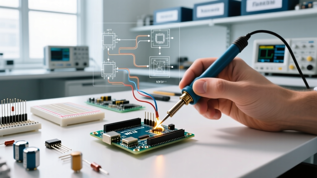
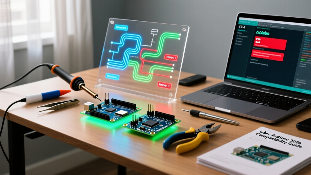
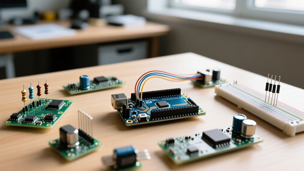
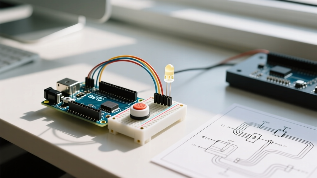
Every electrical engineer and hobbyist has experienced the dreaded 'dead board' scenario. You wire up a sensor array, upload your code, and... nothing happens. When makers search for arduino vs rasberry pi to solve hardware faults, they are usually trying to determine if the failure lies in the microcontroller's bare-metal execution or the single-board computer's Linux environment. In 2026, the landscape is dominated by the Arduino Uno R4 WiFi (powered by the Renesas RA4M1) and the Raspberry Pi 5 (powered by the BCM2712). While both can blink an LED, their error diagnosis pathways are fundamentally different.
This guide bypasses generic comparisons and dives straight into the oscilloscope traces, multimeter readings, and boot codes you need to diagnose catastrophic failures, logic mismatches, and timing jitter across both platforms.
Phase 1: Power and Boot Sequence Diagnostics
The first step in error diagnosis is determining if the board is actually booting. Because one runs a real-time bare-metal loop and the other runs a full desktop OS, their 'signs of life' differ drastically.
Arduino Uno R4: The Bare-Metal Boot
The Arduino Uno R4 does not have an operating system to crash. When you apply 5V via USB or 7-12V via the barrel jack, the Renesas RA4M1 chip begins executing instructions from address 0x0000 almost instantly.
- Symptom: The 'ON' LED is lit, but the 'L' LED (Pin 13) does nothing.
- Diagnosis: If the board gets excessively hot near the USB-C port, you likely fed >5.5V directly into the 5V pin, bypassing the onboard regulator and frying the USB bridge. On the R4 WiFi, the USB bridge is an ESP32-S3. If the ESP32 is dead, the RA4M1 will still run your sketch (the 'L' LED will blink if programmed), but the board will not enumerate on your PC. Use a multimeter to check continuity between the 5V pin and GND; a reading below 10 ohms indicates a shorted voltage regulator.
Raspberry Pi 5: The Linux Boot Sequence
The Pi 5 boots through multiple stages: EEPROM, GPU bootloader (start.elf), and finally the Linux kernel. When the HDMI display remains black, the ACT (Activity) LED is your primary diagnostic tool. According to the official Raspberry Pi boot LED codes, you must count the long and short flashes:
| LED Pattern | Meaning | Diagnostic Action |
|---|---|---|
| 3 Long, 1 Short | SPI EEPROM is corrupted | Use Raspberry Pi Imager to flash the bootloader rescue image. |
| 4 Long, 5 Short | RP1 PCIe link failed | Check for shorts on the PCIe HAT header or remove attached NVMe SSDs. |
| 2 Blinks | start.elf not found | MicroSD card is missing, unformatted, or corrupted. Re-image with FAT32. |
| 7 Blinks | Kernel image not found | The boot partition exists, but kernel8.img is missing or corrupted. |
Pro Tip: If the Pi 5 ACT LED stays solid green but nothing displays, the board has successfully booted to the OS, but your HDMI cable may lack the bandwidth for 4K60Hz, or the display requires a custom config.txt resolution override.
Phase 2: GPIO and Logic Level Faults (The 'Fried Pin' Scenario)
The most common catastrophic error when interfacing sensors occurs when makers ignore logic level thresholds. The Arduino Uno R4 operates at 5V logic, while the Raspberry Pi 5 BCM2712 GPIO pins are strictly 3.3V and are not 5V tolerant.
Diagnosing a Blown GPIO Pin
If you connect a 5V Arduino output directly to a Pi 5 input, the internal protection diodes on the Pi's GPIO will conduct, rapidly overheating and destroying the BCM2712 silicon.
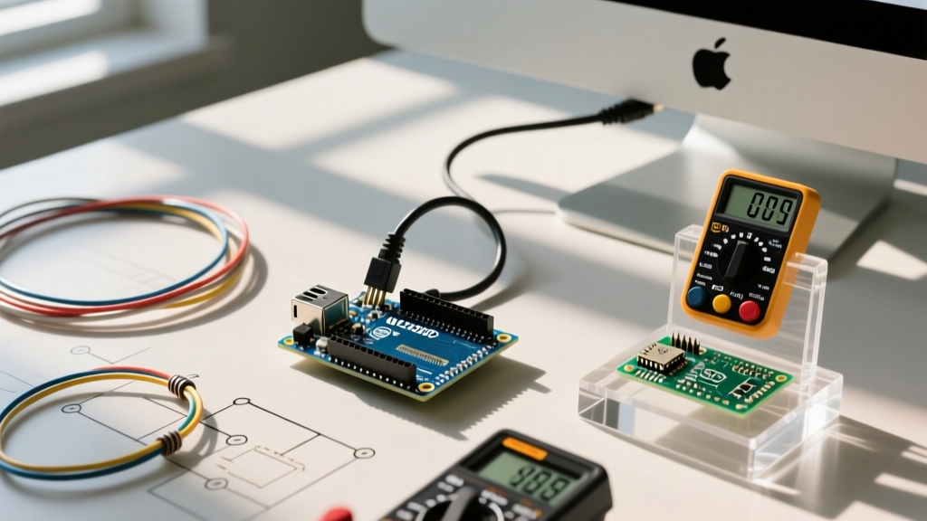
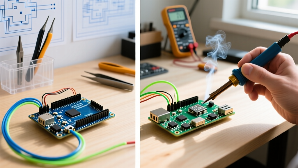
- The Test: Power off both boards. Set your multimeter to continuity/diode mode.
- Measurement: Place the black probe on the Pi's GND pin and the red probe on the suspected GPIO pin.
- Result: A healthy GPIO pin will read a voltage drop of roughly 0.5V to 0.7V (the internal protection diode). If the multimeter beeps (reads near 0.00V), the pin is shorted to ground internally. The chip is permanently damaged.
The Solution: Logic Level Translation
When your error diagnosis points to a voltage mismatch, you must implement a level shifter. As detailed in Adafruit's comprehensive guide to level shifters, the TXS0108E is ideal for bidirectional buses like I2C and UART, while a simple BSS138 MOSFET circuit is preferred for high-speed unidirectional signals like NeoPixel data lines. Never rely on simple resistor voltage dividers for I2C; the parasitic capacitance will ruin the rise times and cause NACK errors.
Phase 3: Timing Jitter and Real-Time Execution Errors
Suppose you are building a robotic arm using WS2812B addressable LEDs and precise PWM motor control. You write the code for the Raspberry Pi 5 using Python, but the LEDs flicker randomly and the motors stutter. Is it a wiring error? No. It is an OS-level scheduling error.
The Linux Interrupt Problem
WS2812B LEDs require a data signal with pulse widths of 0.4µs to 0.8µs. Linux is a non-deterministic, preemptive multitasking OS. A background task (like a Wi-Fi interrupt or a systemd journal write) will pause your Python script for milliseconds at a time. On an oscilloscope, you will see massive jitter in the PWM duty cycle, resulting in corrupted LED colors.
- Raspberry Pi Diagnosis: If your timing-sensitive hardware behaves erratically despite correct wiring, you are hitting kernel interrupt latency. The Pi 5 cannot reliably bit-bang microsecond protocols in user-space.
- Arduino R4 Diagnosis: The Renesas RA4M1 executes instructions in a deterministic loop. A
delayMicroseconds(1)command will consistently take exactly 1 microsecond, every single time, because there is no underlying OS to interrupt it.
The Architectural Fix: Use the Raspberry Pi 5 for high-level pathfinding and computer vision, but offload the microsecond timing requirements to an Arduino via UART or SPI. The Pi sends a simple command ('Move servo to 90 degrees'), and the Arduino handles the precise PWM generation without jitter.
Phase 4: Communication Bus Failures (I2C & UART)
When an I2C sensor (like the BME280) fails to return data, the Arduino IDE Serial Monitor will simply show 'NaN' or 0x00, while the Pi will throw an OSError: [Errno 121] Remote I/O error. Diagnosing this requires understanding bus capacitance and pull-up resistors.
Calculating Pull-Up Resistor Failures
I2C uses open-drain outputs. The bus relies on pull-up resistors to bring the SDA and SCL lines high. If you connect an Arduino (5V) and a Pi (3.3V) to the same I2C bus without a level shifter, the Arduino's 5V pull-ups will back-feed into the Pi's 3.3V rail, potentially damaging the Pi.
Even with correct voltages, Arduino's official hardware documentation notes that the internal pull-ups are roughly 20kΩ to 50kΩ, which is far too weak for high-speed I2C (400kHz).
- Error Signature: I2C devices work at 100kHz but fail with NACK errors at 400kHz.
- Oscilloscope Diagnosis: The rising edge of the SDA/SCL square wave looks like a slow exponential curve (an RC charging curve) rather than a sharp vertical line. The bus capacitance is too high for the weak pull-up resistor.
- The Fix: Disable internal pull-ups in software. Solder external 2.2kΩ or 4.7kΩ resistors between the 3.3V rail and the SDA/SCL lines. Use the formula
R_p = (V_cc - V_ol) / I_olto calculate the exact value based on your specific sensor's sink current limits.
Summary: Choosing the Right Diagnostic Path
Error diagnosis in embedded systems is rarely about 'bad code'; it is almost always a collision between software assumptions and hardware physics. When evaluating Arduino vs Raspberry Pi for your next project, do not just compare CPU clock speeds. Compare their failure modes.
Choose the Raspberry Pi 5 ($80+) when your errors are likely to be high-level software bugs, network timeouts, or database corruptions—environments where you can SSH in, read Linux logs, and patch code on the fly. Choose the Arduino Uno R4 ($27.50) when your errors are likely to be electrical noise, microsecond timing faults, or brownout resets—environments where you need deterministic hardware control and robust 5V logic tolerance. By matching the board's architecture to the expected failure domain, you cut your debugging time in half.