
The Hidden Pitfalls of RC Car Component Mismatches
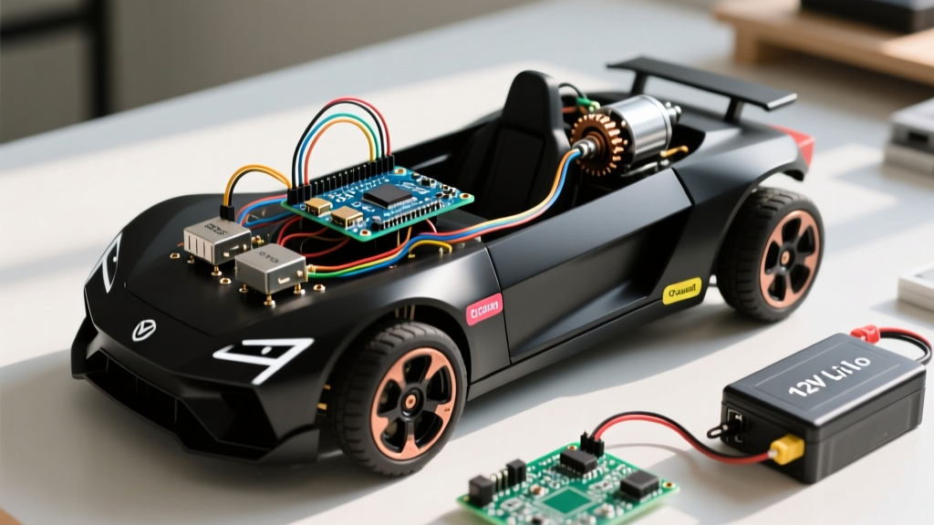
Building a custom arduino control car is a rite of passage for makers, but the journey from a breadboard prototype to a high-speed, reliable RC vehicle is fraught with hardware incompatibilities. The most common point of failure isn't your C++ code; it is a fundamental mismatch in logic levels, power delivery bottlenecks, and PWM frequency conflicts. When you pair a 3.3V microcontroller with a 5V motor driver, or draw too much current through an onboard linear regulator, the result is erratic steering, thermal shutdowns, or the dreaded 'magic smoke'.
This compatibility guide breaks down the exact hardware pairings required to build a robust arduino control car in 2026. We will map microcontrollers to motor drivers, establish strict power architecture rules, and provide a diagnostic matrix for real-world hardware failures.
Microcontroller Selection: Brain-to-Chassis Compatibility
The brain of your arduino control car dictates your logic voltage, processing speed, and wireless capabilities. Choosing the wrong board forces you to add level shifters and external regulators, adding weight and complexity.
Board Comparison Matrix for RC Applications
| Microcontroller | Logic Level | Flash / SRAM | Native Wireless | Best Use Case | Approx. Cost (2026) |
|---|---|---|---|---|---|
| Arduino Uno R4 Minima | 5V | 256KB / 32KB | None | Beginner builds, 5V sensors, simple line-followers | $22.00 |
| Arduino Nano Every | 5V | 48KB / 6KB | None | Compact builds where space is at a premium | $11.50 |
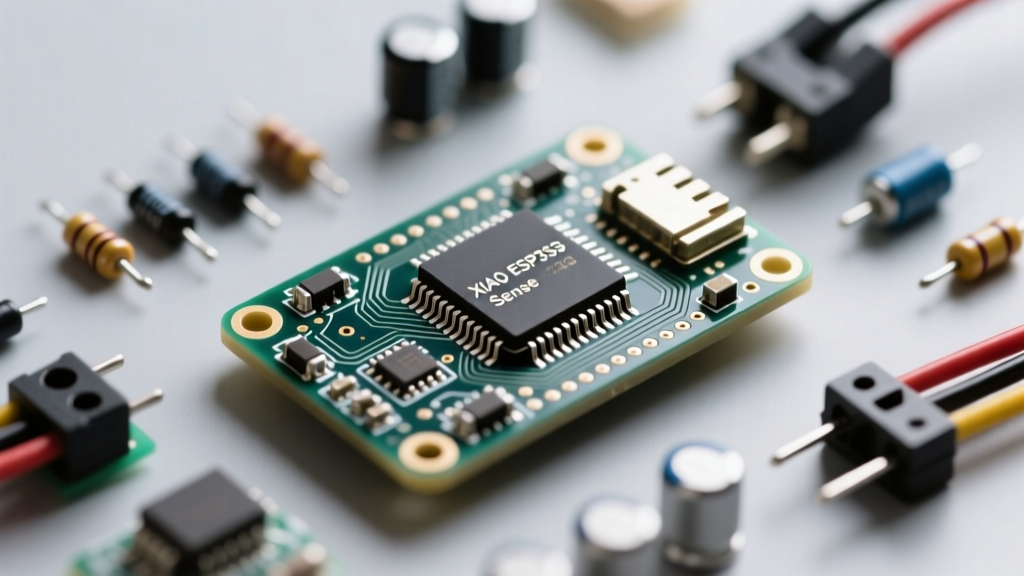
| ESP32-S3 DevKit | 3.3V | 8MB / 512KB | Wi-Fi / BLE | Telemetry, camera integration, ESP-NOW low-latency control | $8.00 - $12.00 |
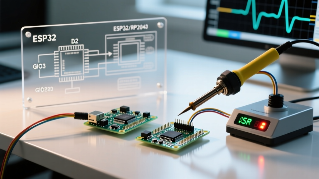
Expert Insight: If you choose the ESP32-S3 for its superior wireless capabilities, you must account for its 3.3V logic. Directly connecting 3.3V GPIO pins to the 5V logic inputs of older motor drivers (like the L298N) will result in unreliable triggering. Use a bidirectional logic level converter (like the BSS138 MOSFET-based modules, costing about $1.50 each) or select 3.3V-tolerant motor drivers.
Motor Driver Matching: Current, Voltage, and PWM Frequencies
The motor driver translates low-current logic signals into high-current motor power. The compatibility between your MCU's PWM (Pulse Width Modulation) frequency and the motor driver's switching characteristics is critical.
The Big Three: L298N vs. TB6612FNG vs. DRV8871
For years, the L298N dual H-bridge was the default for any arduino control car. However, its bipolar transistor design results in a massive voltage drop (typically 1.4V to 2.0V) and poor thermal efficiency. Modern builds demand MOSFET-based drivers.
- TB6612FNG (Dual Channel): The ideal middle-ground. It handles 1.2A continuous current per channel (3.2A peak) with a tiny 0.5V dropout. It requires a PWM frequency between 1kHz and 100kHz. According to the Pololu TB6612FNG specifications, pushing the PWM frequency above 10kHz eliminates the high-pitched whining noise common in RC cars.
- DRV8871 (Single Channel): For high-performance rear-wheel-drive setups requiring massive torque. This TI driver handles up to 3.6A continuous current and operates from 6.5V to 45V. The Texas Instruments DRV8871 Datasheet notes that it requires minimal external components, but you must use two of them for a standard 2WD or 4WD car. It operates flawlessly with the ESP32's default 5kHz PWM.
- L298N (Legacy): Only use this if you are salvaging parts. It requires a minimum of 2.5V logic high, meaning 3.3V MCUs might fail to trigger it reliably under voltage sag. Furthermore, its slow switching speed causes severe heating if PWM frequencies exceed 1kHz.
Power Architecture: Preventing the Dreaded Brownout
The most common reason an arduino control car randomly reboots mid-corner is a power brownout. When motors accelerate, they draw stall current (often 2A to 5A per motor), causing the battery voltage to sag. If this sag drops below the MCU's minimum operating voltage, the system resets.
Battery Chemistry and Voltage Matching
Do not use standard 9V alkaline batteries; their internal resistance is far too high for motor loads. Instead, choose between LiPo and Li-ion configurations:
- 2S LiPo (7.4V Nominal, 8.4V Max): Offers high discharge rates (C-ratings of 25C+). Perfect for high-speed builds. However, 8.4V is dangerously close to the absolute maximum input voltage for the 5V pin on many cheap Nano clones.
- 2S 18650 Li-ion (6.0V - 8.4V): Using two Samsung 25R or Sony VTC6 cells in a 3D-printed sled. Lower discharge rate than LiPo, but safer and longer lifespan. The lower nominal voltage (7.2V) is much friendlier to onboard voltage regulators.
The AMS1117 Thermal Bottleneck
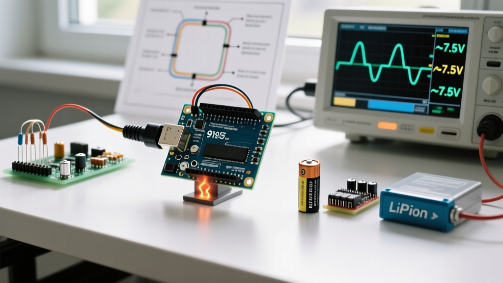
Many makers power their Arduino and servos directly from the board's '5V' or 'VIN' pins. Standard Arduino boards use an AMS1117-5.0 linear regulator. If you supply 8.4V from a fully charged 2S LiPo and draw 300mA for a steering servo and LEDs, the regulator must dissipate the excess voltage as heat.
Heat Dissipation = (8.4V - 5.0V) × 0.3A = 1.02 Watts.
The SOT-223 package on the AMS1117 will trigger thermal shutdown at roughly 1.25W. The fix: Bypass the onboard regulator entirely. Use an MP1584EN buck converter module (costing about $2.00), adjust its potentiometer to output exactly 5.0V, and feed your MCU and servos directly from this dedicated switching regulator.
Telemetry and Remote Control: Wireless Module Pairing
Controlling an arduino control car via smartphone or custom transmitter requires matching the communication protocol to your MCU's hardware UART or SPI buses.
- HC-05 / HC-06 (Bluetooth Classic): Requires a hardware UART. On the Arduino Uno R4, this means using pins 0 and 1, which conflicts with USB serial debugging. Furthermore, these modules operate strictly at 5V logic and 3.3V to 6V power. Connecting them to an ESP32 requires level shifting.
- NRF24L01+ (2.4GHz Transceiver): Communicates via SPI. It is highly sensitive to power noise. The RF power amplifier spikes during transmission, causing brownouts on the MCU's 3.3V rail. Mandatory Compatibility Rule: You must solder a 10µF to 100µF electrolytic decoupling capacitor directly across the VCC and GND pins of the NRF24L01+ module.
- ESP-NOW (ESP32 to ESP32): The ultimate 2026 standard for low-latency RC cars. It bypasses the Wi-Fi stack overhead, delivering sub-5ms latency. It requires no external modules if you use an ESP32 on both the car and the remote, ensuring perfect 3.3V logic compatibility across the entire ecosystem.
Real-World Troubleshooting Matrix
When your arduino control car behaves erratically, use this diagnostic matrix to identify hardware incompatibilities before rewriting your code.
| Symptom | Probable Hardware Root Cause | Actionable Fix |
|---|---|---|
| Car veers sharply to one side at full throttle | PWM deadzone mismatch or ground loop between motor driver and MCU. | Ensure a single, thick star-ground point. Calibrate PWM deadzones in software (e.g., map 0-255 to 10-255). |
| MCU resets when motors suddenly reverse direction | Inductive voltage spike (back-EMF) overwhelming the motor driver's flyback diodes. | Upgrade to a driver with integrated clamp diodes (like DRV8871) or add external Schottky diodes (1N5819) across motor terminals. |
| Bluetooth drops connection when motors spin up | EMI (Electromagnetic Interference) from brushed motors flooding the 2.4GHz spectrum. | Solder 0.1µF ceramic capacitors across the motor terminals and from each terminal to the motor casing. |
| Steering servo jitters at idle | Dirty power from the switching buck converter or shared ground return path. | Separate the high-current motor ground from the low-current logic/servo ground, joining them only at the battery negative terminal. |
Conclusion
Successfully engineering an arduino control car requires looking beyond basic pinout diagrams. By respecting logic level thresholds, abandoning inefficient legacy motor drivers in favor of MOSFET alternatives like the TB6612FNG, and engineering a robust power delivery network with dedicated buck converters, you eliminate 90% of the hardware failures that plague DIY RC projects. For the most up-to-date specifications on modern microcontrollers, always refer to the official Arduino hardware documentation before finalizing your chassis layout.