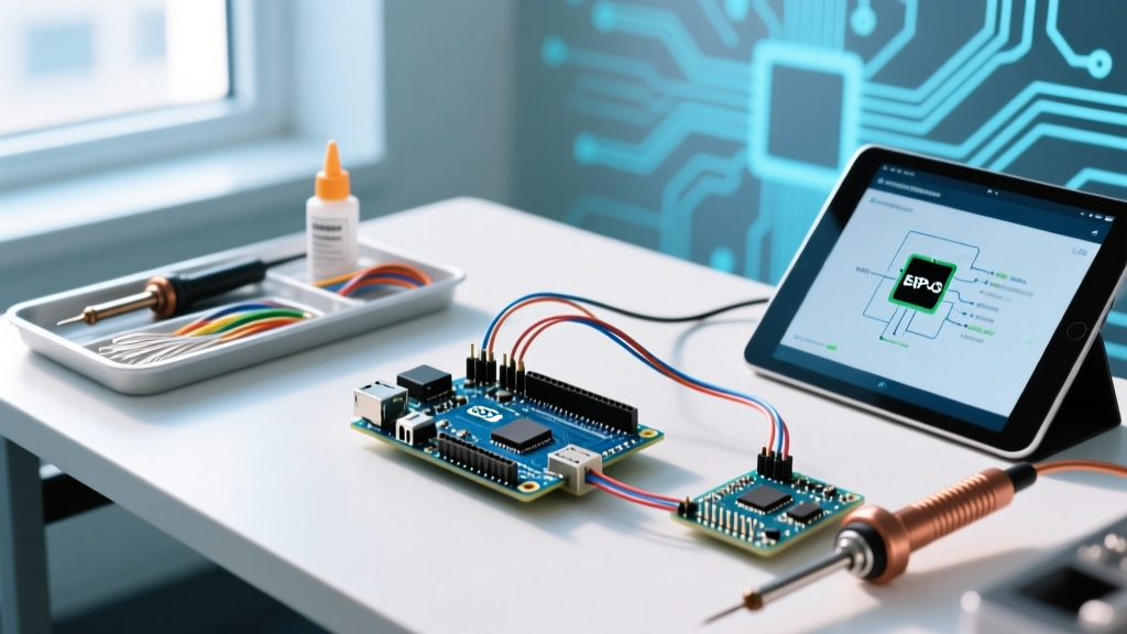

The Engineering Challenge: Sensor Physics vs. MCU Clock Speeds
Building a reliable Arduino speed detector requires more than just wiring a sensor to a digital pin. Velocity measurement—calculated as the change in distance over a specific time delta (v = d/t)—demands precise synchronization between the physical sensor's response time and the microcontroller's interrupt latency. In 2026, with maker projects increasingly integrating into high-speed conveyor systems, slot-car timing tracks, and automated sorting mechanisms, selecting compatible hardware is the difference between a functional prototype and a system plagued by missed triggers and jitter.
This compatibility guide dissects the electrical and architectural requirements for pairing specific speed-detection sensor modules with modern microcontroller units (MCUs). We will cover logic level translation, interrupt overhead, and signal conditioning to ensure your velocity calculations remain accurate down to the millisecond.
Sensor Module Compatibility Matrix
Not all sensors are capable of capturing high-speed events. The sampling rate, physical beam width, and output logic voltage dictate which MCU architectures they can interface with directly. Below is a compatibility and performance matrix for the most common speed-detection modules used in DIY and prosumer electronics.
| Sensor Module | Detection Method | Logic Voltage | Max Switching Freq | Best Use Case | Approx. Cost (2026) |
|---|---|---|---|---|---|
| TCRT5000 (Reflective IR) | Optical Infrared (950nm) | 3.3V - 5V | ~10 kHz | Slot cars, conveyor belts, small object sorting | $1.20 |
| A3144 (Hall Effect) | Magnetic Field Threshold | 4.5V - 24V | ~50 kHz | Rotational speed (RPM), gear tooth counting, magnetic targets | $0.65 |
| HC-SR04 (Ultrasonic) | 40kHz Acoustic Pulse | 5V Only | ~20 Hz | Slow-moving large objects, liquid level change rates | $2.10 |
| RCWL-0516 (Microwave) | Doppler Radar (3.18 GHz) | 3.3V - 5V | N/A (Analog Envelope) | Presence detection (Poor for precise linear velocity without DSP) | $1.50 |
Takeaway: For precise linear speed detection of solid objects, dual-beam TCRT5000 setups or A3144 Hall Effect sensors are mandatory. The HC-SR04 is fundamentally incompatible with high-speed detection due to the speed of sound (~343 m/s) limiting its ping-receive cycle to roughly 50 milliseconds.
Microcontroller Selection: Logic Levels and Interrupt Overhead
The choice of MCU dictates how cleanly you can capture the sensor's state change. Standard polling (using digitalRead() inside a loop()) is entirely insufficient for speed detection. If an object passes through an IR beam in 2 milliseconds, and your main loop takes 5 milliseconds to iterate due to display updates or serial logging, the event is entirely missed. Hardware interrupts are mandatory.
Arduino Uno R4 Minima (Renesas RA4M1)
Replacing the legacy ATmega328P-based R3, the Uno R4 Minima ($27.50) operates at 48 MHz with native 5V logic. This makes it directly compatible with 5V HC-SR04 and raw A3144 Hall sensors without level shifters. Its hardware interrupt latency is exceptionally low, and the micros() function provides 1-microsecond resolution, allowing for highly accurate time-delta calculations between two spatially separated sensors.
ESP32-WROOM-32 DevKit
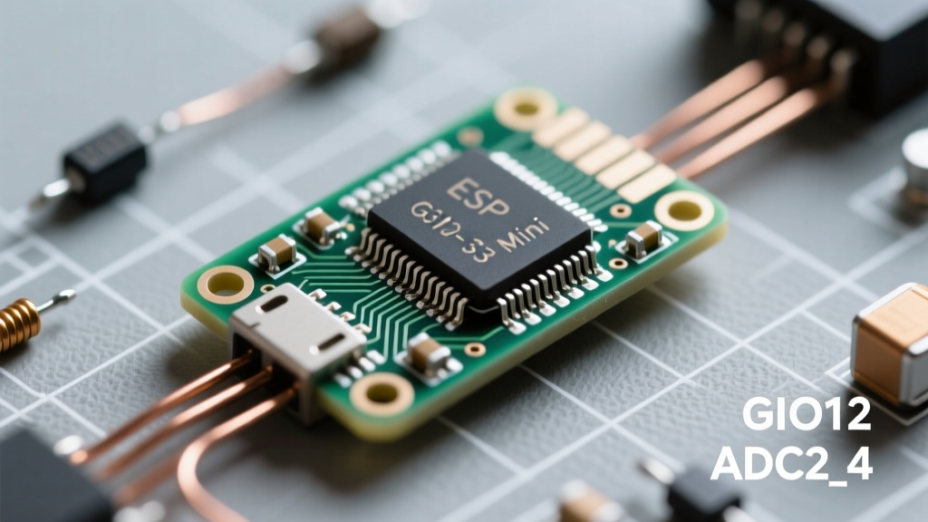
Priced around $5.50, the ESP32 offers dual-core processing at 240 MHz, making it ideal for calculating complex moving averages or pushing speed data to MQTT brokers via Wi-Fi. However, the ESP32 operates strictly on 3.3V logic. Feeding a 5V trigger signal from an HC-SR04 or an unregulated A3144 directly into an ESP32 GPIO pin will degrade the silicon over time or cause immediate catastrophic failure.
Crucial Edge Case: 5V to 3.3V Logic Translation
When pairing 5V sensors with 3.3V MCUs (like the ESP32, Arduino Nano 33 IoT, or Raspberry Pi Pico), you must implement logic level translation. A simple resistor voltage divider is often too slow for high-frequency signals due to parasitic capacitance, which rounds off the sharp square-wave edges required for clean interrupt triggering.
Engineering Rule of Thumb: For any speed detector operating above 1 kHz (e.g., counting gear teeth or high-speed conveyor sorting), abandon resistor dividers. Use a dedicated BSS138 MOSFET-based bidirectional logic level converter breakout board (approx. $1.50) or a high-speed optocoupler like the 6N137 to isolate the sensor from the MCU while preserving edge sharpness.
For comprehensive guidelines on protecting low-voltage microcontrollers from higher-voltage sensor arrays, refer to the foundational principles outlined in SparkFun's Logic Levels Tutorial.
Velocity Calculation: Hardware Interrupts Over Polling
To measure speed, you need two sensors placed at a known, fixed distance apart (e.g., 10.0 cm). When the object breaks Beam A, an Interrupt Service Routine (ISR) records the timestamp. When it breaks Beam B, a second ISR records the final timestamp.
The Math and the Code Logic
Using the Arduino attachInterrupt() API, you map physical pins to ISR functions. The velocity calculation occurs outside the ISR to prevent blocking the processor.
- Distance (d): 0.1 meters (10 cm fixed physical gap)
- Time Delta (Δt):
time_B - time_A(measured in microseconds) - Velocity (v):
0.1 / (Δt / 1000000.0)= meters per second
Critical Implementation Detail: Variables shared between the ISR and the main loop (like time_A and time_B) must be declared as volatile. Furthermore, on 8-bit or 32-bit architectures, reading a multi-byte variable (like a 32-bit unsigned long from micros()) inside the main loop while an interrupt could fire mid-read requires temporarily disabling interrupts using noInterrupts() and interrupts() to prevent data tearing.
Real-World Failure Modes & Signal Conditioning
Even with the correct MCU and sensor pairing, environmental factors will introduce catastrophic errors into your speed calculations if left unaddressed. Below are the most common failure modes and their hardware-level solutions.
- Switch Bounce and Optical Jitter: Reflective IR sensors (TCRT5000) suffer from analog transition zones. As an object enters the beam, the phototransistor's output voltage drifts slowly through the MCU's digital threshold voltage (typically ~2.5V for 5V logic). This causes the MCU to register dozens of rapid-fire interrupts for a single object pass.
Solution: Route the analog sensor output through a Schmitt Trigger IC (like the 74HC14 hex inverter). This introduces hysteresis, ensuring a single, razor-sharp digital edge regardless of how slowly the object enters the beam. - Electromagnetic Interference (EMI): If your speed detector is mounted near DC motors, VFDs, or relays, long unshielded sensor wires will act as antennas, picking up noise and generating phantom interrupts that result in impossibly high speed readings.
Solution: Use twisted-pair cabling for sensor runs exceeding 30 cm. Place a 100nF ceramic decoupling capacitor directly across the VCC and GND pins at the sensor head, and add a 1kΩ pull-up resistor at the MCU input pin. - ISR Overhead and Micros Rollover: The
micros()function overflows approximately every 70 minutes on standard Arduino boards. If an object enters Beam A, and the system waits past the rollover point before hitting Beam B, the time delta calculation will result in a massive negative number, breaking your math.
Solution: Always calculate time deltas using unsigned arithmetic:unsigned long delta = time_B - time_A;. In C/C++, unsigned integer underflow naturally wraps around, yielding the correct elapsed time even across a rollover event.
Authoritative References
For deeper architectural specifications regarding GPIO limitations and interrupt handling on modern microcontrollers, consult the following documentation:
- Arduino Language Reference: attachInterrupt() - Official documentation on mapping hardware interrupt vectors to digital pins.
- SparkFun Logic Levels Tutorial - Essential reading for understanding 3.3V vs 5V logic thresholds and safe translation methods.
- Espressif ESP-IDF GPIO API Reference - Detailed technical constraints on ESP32 pin capacitance, drive strength, and interrupt latency.