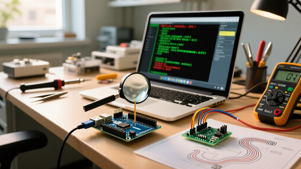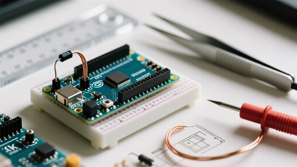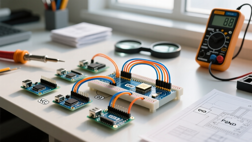

The Undisputed King of Rapid Prototyping
Despite the plummeting costs of custom PCB manufacturing and the rise of perfboards, the solderless Arduino bread board remains the undisputed champion of rapid iteration in 2026. Whether you are debugging an I2C sensor array, testing a new motor driver shield, or simply learning the basics of microcontroller GPIO, a high-quality breadboard is the foundation of your electronics workbench. However, not all prototyping boards are created equal. The maker community has long battled cheap clones suffering from oxidized contacts, loose tie-points, and severe power rail voltage drops.
In this community resource roundup, we synthesize insights from veteran electrical engineers, popular maker forums, and rigorous bench testing to bring you the ultimate guide to selecting, wiring, and troubleshooting your Arduino bread board setups.
2026 Community-Vetted Arduino Bread Board Models
The market is saturated with generic, unbranded solderless boards. While a $4 generic board might suffice for a simple LED blink, complex MCU circuits demand reliable phosphor-bronze or nickel-silver contacts. Below is a comparison of the top-tier models recommended by the Arduino General Electronics community and professional prototypers.
| Model | Tie-Points | Contact Material | Est. Price (2026) | Best Use Case |
|---|---|---|---|---|
| BusBoard Prototype Systems BB400 | 400 (Dual strip) | Nickel-Silver | $12.95 | Compact IoT nodes, ESP32/Arduino Nano projects |
| Elenco 9425 | 830 (Full size) | Phosphor-Bronze | $14.50 | Complex wiring, multiple shields, UNO/Mega projects |
| Global Specialties PB-103 | 630 | Beryllium-Copper | $18.00 | High-reliability lab environments, education |
| Makeronics Transparent | 830 | Standard Alloy | $9.99 | Visual wire tracing, beginner tutorials |
Community Pro-Tip: 'Never buy multi-packs of unbranded boards from generic marketplaces for critical MCU debugging. The contact resistance variance between rows on cheap boards can introduce phantom voltage drops that take hours to trace.' — Senior EEVblog Forum Contributor
Hidden Failure Modes in Solderless Prototyping
When an Arduino sketch behaves erratically on a breadboard but works perfectly once soldered, the culprit is almost always the physical interface of the breadboard itself. Understanding these failure modes is critical for advanced makers.
1. The Parasitic Capacitance Trap
Every solderless breadboard introduces parasitic capacitance between adjacent rows, typically ranging from 2pF to 5pF. While negligible for basic digital I/O or low-speed UART, this capacitance becomes a massive bottleneck for high-speed protocols. If you are routing SPI buses above 4MHz or high-speed I2C, the capacitive coupling between adjacent signal traces will round off your square waves, leading to data corruption. The Fix: Always route high-speed clock lines (SCK, SCL) with an empty row or a grounded wire between them and the data lines (MOSI, SDA) to act as an electrostatic shield.
2. Contact Oxidation and Micro-Fretting
The internal leaf-spring contacts rely on mechanical friction to grip your component leads. Over time, exposure to ambient humidity causes micro-oxidation. Furthermore, repeatedly inserting and removing 22AWG wires causes 'micro-fretting,' wearing down the contact plating. According to the comprehensive SparkFun Breadboard Tutorial, using contact cleaner (like DeoxIT) and avoiding abrasive tools to clean contacts will extend the lifespan of premium boards by years.
Power Rail Sagging and the Voltage Drop Trap
One of the most frequent issues reported in the official Arduino Foundations documentation is the 'brownout reset'—where the microcontroller randomly restarts under load. This is rarely a code issue; it is almost always a power distribution failure on the breadboard.
- The Internal Bottleneck: The thin metal strips running down the power rails of a standard breadboard are not designed to carry high current. Pushing more than 1A through a standard 830-point board's power rail will result in significant voltage sag and localized heating.
- The Wire Gauge Rule: Always use 22 AWG solid-core copper wire for breadboard jumpers. 24 AWG is too thin and can bend inside the contact, causing intermittent opens. 20 AWG is too thick and will permanently stretch the leaf-springs, ruining the board for future smaller components.
- Decoupling Strategy: Never rely solely on the breadboard's power rails for decoupling. Place a 100nF ceramic capacitor as physically close to the VCC and GND pins of your Arduino or external ICs as possible, bypassing the high resistance of the long power rail strips.
Essential Community Wiring Hacks for 2026
Veteran makers have developed specific workflows to keep their Arduino bread board layouts clean, debuggable, and reliable. Implement these strategies on your next build:
- Ditch the Pre-Formed Jumper Kits: While those rainbow-colored, pre-bent jumper wire kits look neat, they force you to route wires over the top of your ICs, blocking visibility and making probing with a multimeter impossible. Instead, buy a spool of 22 AWG solid-core wire in 4 colors (Red, Black, Yellow, Blue) and cut/strip them to exact lengths using an automatic wire stripper.
- The 'Ground Plane' Technique: For mixed-signal circuits (e.g., reading analog sensors while driving PWM motors), dedicate one entire side of the breadboard exclusively to digital grounds, and the other to analog grounds, joining them at a single 'star ground' point near the Arduino's GND pin.
- Color Coding Standards: Adopt the community standard: Red for +5V/VCC, Black for GND, Yellow/Orange for digital signals, and Blue/Green for analog signals. This reduces cognitive load when tracing faults with an oscilloscope probe.
Top Community Resources & Deep-Dive Tutorials
To further master your prototyping workflow, bookmark these community-trusted resources:
- Arduino Official Hardware Guides: The Arduino Breadboard Foundations page remains the best visual primer for understanding internal node connections and power bus routing.
- SparkFun & Adafruit Learn Systems: Both companies maintain exhaustive, continuously updated guides on breadboarding best practices, including how to safely interface 3.3V logic sensors with 5V Arduino boards using breadboard-friendly logic level shifters.
- EEVblog Forums (General Electronics): For advanced troubleshooting—such as diagnosing ground loops on breadboards or measuring contact resistance with a 4-wire Kelvin measurement—the EEVblog community provides unparalleled professional-grade advice.
Frequently Asked Questions
Can I use stranded wire in an Arduino bread board?
Generally, no. Stranded wire frays when inserted into solderless contacts, leading to broken strands that can short adjacent rows. If you must use stranded wire, you need to crimp a ferrule or tin the tip with solder (though tinned tips can deform and loosen over time, making ferrules the superior choice).
Why does my I2C OLED display fail on the breadboard but work when directly wired?
I2C requires pull-up resistors (usually 4.7kΩ). On a breadboard, the added parasitic capacitance of the long jumper wires and the breadboard's internal contacts slows down the rise time of the SDA/SCL signals. Try lowering your pull-up resistors to 2.2kΩ or reducing the I2C clock speed in your Arduino Wire library to 100kHz to compensate for the breadboard's capacitance.
How do I test if a specific breadboard row is dead?
Use a digital multimeter in continuity mode. Insert a known-good piece of 22 AWG wire into the suspected row, and another into a different hole in the same 5-hole node. If the multimeter does not beep, or if the resistance reads higher than 0.5 ohms, the internal leaf-spring is either bent, oxidized, or broken. Mark the row with a red sharpie and avoid using it.