
The Reality of Off-Grid Microcontroller Power
Designing an Arduino powered by solar seems straightforward in a controlled lab environment, but field deployment often reveals critical power management flaws. When your remote weather station or soil moisture sensor fails after the first cloudy week, the root cause is rarely a defective solar panel. Instead, the failure usually stems from mismatched charge controller topologies, unoptimized Brown-Out Detection (BOD) thresholds, or parasitic quiescent currents draining the battery overnight.
This troubleshooting guide addresses the three most common failure modes in solar-powered Arduino projects. We will bypass generic advice and focus on exact hardware modifications, firmware-level register tweaks, and precise multimeter diagnostics to ensure your off-grid MCU survives the worst weather conditions of 2026 and beyond.
Symptom 1: The 'Phantom Reset' (Brownout Detection Failures)
If your Arduino randomly reboots at dawn, or immediately when a peripheral like a relay or soil sensor activates, you are likely hitting a Brown-Out Detection (BOD) threshold. The ATmega328P microcontroller features an internal BOD circuit that triggers a hardware reset if the supply voltage drops below a specific level (typically 2.7V, 4.3V, or 1.8V depending on the fuse settings).
The Edge Case: LDO Dropout vs. Solar Sag
When a high-current sensor wakes up from sleep, it can pull 150mA for a few milliseconds. If your power rail relies on a standard linear Low Dropout (LDO) regulator fed by a partially depleted 18650 Li-ion cell (e.g., 3.4V), the LDO will experience a transient voltage sag. If the 3.3V rail dips to 2.6V for even 10 microseconds, the BOD triggers a reset, trapping your Arduino in a perpetual boot-loop because the boot sequence itself draws peak current.
Actionable Fixes for Phantom Resets
- Hardware Buffer: Solder a 470µF low-ESR capacitor (such as the Panasonic FR series, ~$0.40 each) directly across the 3.3V and GND pins on your Arduino Pro Mini or custom PCB. This provides the instantaneous current burst needed to ride out the LDO dropout.
- Firmware BOD Disable: According to the official Microchip ATmega328P datasheet, the BOD circuit consumes roughly 20µA of continuous current. In your sleep function, disable the BOD via software right before entering power-down mode using the MCUCR register. This not only prevents sleep-mode brownouts but also saves critical microamps.
- Lower the BOD Threshold: If you are using avrdude to flash your bootloader, change the extended fuse byte to set the BOD level to 1.8V instead of 2.7V. This allows the MCU to operate deeper into the lithium-ion discharge curve safely.
Symptom 2: Battery Never Reaches 4.2V (Charge Controller Bottlenecks)
A frequent complaint among makers is that their 18650 battery voltage stalls at 3.8V or 3.9V, even after days of full sunlight. This is almost always caused by using the wrong charge controller topology for the specific solar panel's IV (Current-Voltage) curve.
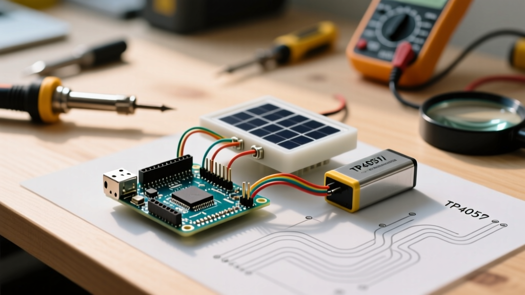
The ubiquitous TP4056 module (usually priced around $1.50) is a linear charger. It operates by pulling the solar panel's voltage down to match the battery's current voltage. If you pair a 6V 3W polycrystalline panel with a TP4056 and a 3.7V battery, the panel is forced to operate at 3.7V. However, a '6V' panel's Voltage at Maximum Power (Vmp) is actually around 5.5V. By dragging the panel down to 3.7V, you move far left on the IV curve, reducing the panel's actual power output from 3W to less than 0.8W. The battery simply isn't receiving enough current to reach the 4.2V constant-voltage (CV) charging phase.
Charge Controller Comparison & Selection
| Module / IC | Topology | Typical Cost | Best Use Case | Major Limitation |
|---|---|---|---|---|
| TP4056 | Linear | $1.00 - $1.50 | USB charging or massive oversized panels | No MPPT; drags panel Vmp down to battery voltage, wasting up to 60% of harvest. |
| CN3791 | PWM Buck (MPPT-like) | $4.00 - $6.00 | 1S Li-ion with 5V-7V solar panels | Requires manual trim-pot tuning to match the specific panel's Vmp. |
| BQ25895 | Switch-Mode with true MPPT | $8.00+ (IC only) | High-efficiency commercial IoT nodes | Complex I2C configuration; difficult for hobbyist breadboarding. |
The Fix: Tuning a CN3791 MPPT Module
As detailed in Adafruit's solar charging guides, matching the panel's maximum power point is critical for low-wattage setups. Replace your TP4056 with a CN3791-based solar charge module. Once installed, follow this tuning procedure:
- Disconnect the battery and the Arduino load.
- Connect the solar panel to the CN3791 input.
- Place your multimeter probes on the CN3791 input terminals (VIN and GND).
- Using a small ceramic flathead screwdriver, adjust the blue trim potentiometer until the multimeter reads the exact Vmp printed on the back of your solar panel (usually 5.5V or 6.0V for standard hobby panels).
- Reconnect the battery. The CN3791 will now hold the panel at its peak efficiency point, easily pushing the battery to 4.2V.
Symptom 3: Nighttime Drain Exceeds Solar Harvest
If your system works in summer but dies in winter, your nighttime parasitic drain is exceeding your daily solar harvest. A standard Arduino Nano or Uno is fundamentally incompatible with off-grid solar survival. The onboard 5V LDO quiescent current, combined with the USB-to-Serial chip (CH340 or FT232), draws a baseline of 15mA to 25mA even when the microcontroller is in deep sleep.
Rule of Thumb: A 20mA continuous drain consumes 480mAh per day. A standard 6V 1W solar panel in Northern Europe during December might only yield 50mAh to 80mAh per day. The math guarantees system death within 48 hours.
Eliminating Parasitic Drain
To fix this, you must audit every component on your board. If you are using a Seeeduino XIAO (ATSAMD21) or a barebones ATmega328P on a custom PCB, your sleep current should be under 15µA. If you are measuring 2mA or higher, check the following:
- Remove Power LEDs: Desolder the onboard power LED and its current-limiting resistor. This alone saves 2mA to 5mA.
- Bypass Voltage Regulators: If you are feeding a 3.3V Arduino directly from a 1S Li-ion cell (4.2V to 3.0V), bypass the onboard LDO entirely by feeding the raw 3.3V pin, eliminating the LDO's ground-pin quiescent current.
- Implement Load Switching: Sensors like the BME280 or capacitive soil moisture sensors leak current through their I2C/SPI pull-up resistors when powered continuously. Use a P-Channel MOSFET (like the AO3401, ~$0.15) controlled by a GPIO pin to completely sever power to the sensors when the MCU is sleeping.
Power Budget Calculation Matrix
Before deploying, calculate your exact energy budget. For geographic solar irradiance data to calculate your baseline harvest, rely on the NREL Solar Resource database to find the worst-case Peak Sun Hours (PSH) for your zip code.
| Parameter | Variable | Example Value (Winter Scenario) |
|---|---|---|
| Solar Panel Rated Power | P_rated | 3.5W (6V Monocrystalline) |
| Worst-Case Peak Sun Hours | PSH | 1.2 Hours / Day |
| System Efficiency (MPPT + Wiring) | Eff | 75% (0.75) |
| Daily Harvest | P_rated * PSH * Eff | 3.15 Wh / Day |
| MCU Sleep Current | I_sleep | 15 µA (0.000015 A) |
| Active Time per Day | T_active | 5 mins (0.083 Hours) |
| Active Current | I_active | 12 mA (0.012 A) |
| Daily Drain | (I_sleep * 24) + (I_active * T_active) | ~0.37 Wh / Day |
In this scenario, your 3.15 Wh harvest easily covers the 0.37 Wh drain, leaving an 88% surplus to recharge the battery after cloudy days. If your daily drain calculation exceeds 60% of your worst-case harvest, you must increase panel size or optimize firmware sleep times.
Diagnostic Multimeter Checklist
When troubleshooting a dead node in the field, follow this exact probing sequence with your digital multimeter (DMM):
- Probe Panel Voc: Disconnect the panel from the charge controller. Measure open-circuit voltage in direct sun. If it reads less than 80% of the rated Voc, the panel has micro-cracks or severe delamination and must be replaced.
- Probe Charge Controller Output: Reconnect the panel. Measure the battery terminals on the controller. If it reads exactly the battery's resting voltage (e.g., 3.7V) and does not rise to 4.15V+ over an hour, the controller is either faulty, or the panel Vmp is mismatched (see CN3791 tuning above).
- Measure True Sleep Current: Disconnect the battery. Place your DMM in series between the battery positive terminal and the PCB VIN, set to the µA range. Force the Arduino into sleep mode via serial command or wait for the sleep cycle. If the reading fluctuates or stays above 50µA, a peripheral is leaking current.
Frequently Asked Questions
Can I use a standard 12V solar panel with a 5V Arduino?
Not directly without severe efficiency losses. Running a 12V panel (Vmp ~18V) into a linear 5V LDO to power an Arduino will result in the LDO dissipating over 70% of the harvested energy as heat. Instead, use a buck converter module based on the MP2315 or TPS5430 to step the 12V down to 5V with >90% efficiency before it reaches the Arduino.
Why does my Arduino freeze when the solar panel is shaded?
When a solar panel is completely shaded, it can act as a parasitic load, drawing current backward from the battery. While most charge controllers have reverse-current protection, low-cost modules often use a Schottky diode that leaks microamps or fails to block reverse voltage entirely. Ensure your charge controller explicitly features reverse-discharge protection, or add a 1N5819 Schottky diode in series with the panel's positive lead.
Is Super Capacitor buffering better than Li-ion for solar MCUs?
For ultra-low-power nodes (under 10µA sleep) that only need to survive a few hours of darkness, supercapacitors (e.g., 10F 5.5V) offer infinite charge cycles and operate in extreme sub-zero temperatures where Li-ion chemistry fails. However, for standard Arduinos drawing milliamps, Li-ion 18650 cells provide vastly superior energy density and are the mandatory choice for multi-day autonomy.