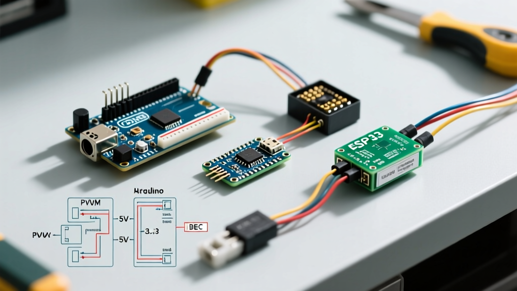

The Hidden Complexity of Arduino ESC Integration
Connecting an Electronic Speed Controller (ESC) to a microcontroller seems trivial on paper: wire the signal pin, share a ground, and send a PWM pulse. In practice, mismatched logic levels, inadequate Battery Eliminator Circuit (BEC) current limits, and incompatible firmware protocols cause roughly 90% of all motor control failures in DIY robotics and drones. As of 2026, the landscape of ESC firmware has shifted heavily toward digital protocols like DShot and open-source firmware like AM32, making board selection more critical than ever.
This compatibility guide cuts through the guesswork, providing exact hardware pairings, logic-level shifting requirements, and power budgeting frameworks to ensure your Arduino, ESP32, or Teensy reliably drives brushless and brushed motors without frying your silicon.
The Logic Level Bottleneck: 5V vs 3.3V Microcontrollers
The most common point of failure when pairing modern microcontrollers with standard RC ESCs is the logic level mismatch. Most legacy and budget ESCs (such as the Hobbywing Skywalker 20A or Turnigy Basic 18A) utilize an internal opto-isolator or a simple transistor-resistor network on the signal input. These circuits were designed for the 5V logic outputs of standard ATmega328P-based boards.
Why 3.3V Boards Fail with Opto-Isolated ESCs
If you are using an ESP32, Arduino Due, or Teensy 4.1, your GPIO pins output 3.3V. While the Arduino Servo Library Documentation suggests that standard servos and ESCs recognize anything above 2.5V as a HIGH signal, opto-isolated ESCs are different. The internal infrared LED inside the opto-coupler requires a specific forward voltage (typically 1.2V to 1.5V) plus enough current to trigger the phototransistor. A 3.3V pin often cannot source enough current through the ESC's internal current-limiting resistor to reliably trigger the opto-isolator, resulting in erratic arming or complete signal dropout.
The Compatibility Matrix: Board to ESC Logic Matching
| Microcontroller | Logic Level | Standard 5V ESC (Non-Opto) | Opto-Isolated ESC | Required Hardware Fix |
|---|---|---|---|---|
| Arduino Uno / Nano | 5V | Native Compatible | Native Compatible | None |
| ESP32 (DevKit V1) | 3.3V | Usually Compatible | Fails / Erratic | 74AHCT125 Level Shifter |
| Teensy 4.1 | 3.3V | Usually Compatible | Fails / Erratic | 74AHCT125 Level Shifter |
| Arduino Portenta H7 | 3.3V | Usually Compatible | Fails / Erratic | 74AHCT125 Level Shifter |
Actionable Fix: Never use a simple voltage divider to step up 3.3V to 5V for high-frequency PWM; the parasitic capacitance of the resistors will round off the square wave edges, confusing the ESC. Instead, use a dedicated logic level shifter IC like the 74AHCT125 or a bidirectional MOSFET-based converter (e.g., SparkFun's BSS138 breakout, roughly $3.50) powered by the ESC's 5V BEC on the VCC side.
PWM Protocols and Refresh Rates in 2026
The era of relying solely on standard 50Hz analog PWM is ending for high-performance applications. When matching an Arduino-family board to an ESC, you must align the board's hardware timer capabilities with the ESC's firmware protocol. According to the comprehensive Oscar Liang ESC Protocol Guide, digital protocols eliminate the signal jitter inherent in analog PWM.
Protocol Compatibility Breakdown
- Standard PWM (50Hz - 400Hz): Pulse width varies from 1000µs to 2000µs. Fully supported by all Arduino boards via the
<Servo.h>library. Best for slow-moving robotics, RC boats, and basic throttle control. - OneShot125: Reduces pulse width to 125µs - 250µs. Requires hardware timer interrupts. Supported on ATmega328P (Uno/Nano) but consumes valuable timer resources, often conflicting with other libraries like
<IRremote.h>. - DShot (Digital Shot): A fully digital protocol (DShot150, 300, 600) that sends binary packets. It is immune to electrical noise and eliminates the need for ESC calibration. Compatibility Warning: Standard Arduino Unos cannot reliably bit-bang DShot600 without severe timing jitter. For DShot, you must use an ESP32 or Teensy utilizing Direct Memory Access (DMA) to handle the precise microsecond timing.
If you are building a modern drone or high-speed rover in 2026, pair an ESP32-S3 with an ESC running AM32 or BLHeli_32 firmware to leverage bidirectional DShot, which allows the ESC to send real-time RPM telemetry back to the microcontroller over the same signal wire.
Powering the Arduino: BEC Limits and Voltage Spikes
Most ESCs feature a built-in Battery Eliminator Circuit (BEC) that steps down the main battery voltage (e.g., 11.1V from a 3S LiPo) to 5V to power the receiver and flight controller. However, relying on an ESC's internal linear BEC to power an Arduino and peripheral sensors is a frequent cause of thermal shutdowns.
The Thermal Trap of Linear BECs
Budget ESCs (like the generic 30A blue-brushless models found on Amazon for ~$12) use linear BECs. A linear BEC dissipates excess voltage as heat. The thermal dissipation formula is: Heat (Watts) = (Vin - Vout) * Current.
If you are running a 4S LiPo (14.8V) and your Arduino Nano + OLED display + two micro servos draw 400mA (0.4A), the linear BEC must dissipate: (14.8V - 5V) * 0.4A = 3.92 Watts. Most internal linear BECs are only rated for 1W to 2W of thermal dissipation before they overheat and drop the 5V rail, causing your Arduino to brownout and reset mid-flight.
Expert Rule of Thumb: If your total 5V logic draw exceeds 200mA, or you are running a battery above 3S (11.1V), completely ignore the ESC's built-in 5V red wire. Cut it back, tape it, and power your Arduino using a dedicated switching UBEC (Universal Battery Eliminator Circuit), such as the Hobbywing 5V/3A Switching UBEC (~$8.00), which operates at 90% efficiency and eliminates the thermal trap.
Step-by-Step: Wiring and Calibrating a Standard ESC
When using standard analog PWM, every ESC requires an arming sequence and throttle range calibration. If you skip this, the ESC will interpret the Arduino's 1000µs idle signal as a mid-throttle command and refuse to arm, emitting a continuous warning beep.
Hardware Wiring (Arduino Nano to Hobbywing Skywalker 40A)
- Signal Wire (White/Yellow): Connect to Arduino Pin D9 (a hardware PWM capable pin).
- Ground Wire (Black): Connect to Arduino GND. Crucial: Without a shared ground, the PWM signal has no reference voltage and will not work.
- 5V BEC Wire (Red): Connect to Arduino 5V pin ONLY if you are using a 2S or 3S battery and drawing less than 200mA. Otherwise, leave it disconnected.
- Main Power (Thick Red/Black): Connect directly to the battery and motor phases (A, B, C).
The Calibration Routine
Before running your main operational code, you must flash a calibration sketch. The ESC needs to learn what your specific Arduino considers '0% throttle' and '100% throttle'.
#include <Servo.h>
Servo esc;

void setup() {
  esc.attach(9, 1000, 2000); // Pin 9, 1000us min, 2000us max
  esc.writeMicroseconds(2000); // Send max throttle
  // POWER ON THE ESC NOW. Wait for the 'beep-beep' confirmation tone.
  delay(3000);
  esc.writeMicroseconds(1000); // Send min throttle
  // Wait for the descending arming tone.
}

void loop() {
  // Calibration complete. ESC is now armed.
}
Troubleshooting Edge Cases and Failure Modes
Continuous Beeping on Power-Up
Symptom: ESC powers on but emits a steady, repeating beep and the motor will not spin.
Diagnosis: The ESC is not detecting a valid 0% throttle (1000µs) signal. This happens if the Arduino boots slowly and the ESC times out waiting for the idle signal, or if your code initializes the Servo object at 1500µs (mid-stick).
Fix: Ensure esc.writeMicroseconds(1000); is called in the setup() function before any delays or sensor initialization routines.
Motor Stutters or Cogs at Low Throttle
Symptom: Smooth operation at high RPM, but violent shaking or 'cogging' between 1000µs and 1150µs.
Diagnosis: Analog PWM jitter caused by software interrupts on the Arduino. Functions like delay(), Serial.print(), or software-based I2C libraries can disrupt the 50Hz timer interrupt that generates the PWM wave.
Fix: Move to an ESP32 and utilize the LEDC (LED Control) hardware PWM peripheral, which operates entirely independently of the main CPU cores, guaranteeing a jitter-free signal regardless of your code's blocking operations.
Back-EMF Destroying the Microcontroller
Symptom: Arduino randomly resets or the voltage regulator burns out when the motor brakes or decelerates rapidly.
Diagnosis: When a brushless motor decelerates, it acts as a generator, sending high-voltage Back-EMF spikes back through the ESC's BEC and into the Arduino's 5V rail.
Fix: Install a 1000µF 25V low-ESR electrolytic capacitor across the main battery terminals on the ESC, and add a 5.1V Zener diode across the Arduino's 5V and GND pins to clamp transient voltage spikes.