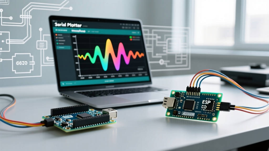

The Deceptive Simplicity of analogRead()
At first glance, reading a sensor with an Arduino seems trivial. You wire a component to an A0 pin, call analogRead(), and expect a clean integer between 0 and 1023. However, real-world electrical environments are inherently hostile to high-impedance analog signals. When your Arduino read analog input returns erratic jumps, slow drift, or stuck values, the issue rarely lies in the code itself. Instead, it stems from a mismatch between the microcontroller's internal Analog-to-Digital Converter (ADC) architecture and the physical realities of your circuit.
In this error diagnosis guide, we will bypass basic syntax troubleshooting and dive deep into the hardware and firmware-level failure modes that corrupt ADC data on ATmega328P-based boards (like the Uno R3/Nano) and modern ESP32 variants.
Symptom 1: Random 0-1023 Spikes (The Floating Pin Phantom)
The Error: You unplug a sensor, or leave an analog pin unconnected, and the serial monitor spits out wild, random numbers spanning the entire 0-1023 range.
The Diagnosis: This is the classic 'floating pin' phenomenon, but understanding why it happens requires looking inside the ATmega328P. The ADC uses a multiplexer to route different pins to a single internal Sample-and-Hold (S/H) capacitor, which is roughly 14pF. When you read an unconnected pin, the S/H capacitor retains the residual charge from the previously read pin. Because a floating pin has near-infinite impedance, it cannot source or sink the current required to overwrite that residual charge.
The Fix: Never leave analog pins floating in high-EMI environments. If a pin is temporarily unused in your code, initialize it with a 10kΩ pull-down resistor to ground. If you are multiplexing multiple high-impedance sensors, you must insert a 'dummy read' in your software. Read the target pin twice in a row and discard the first value; this gives the internal 14pF capacitor an extra 1.5 ADC clock cycles to charge to the correct voltage.
Symptom 2: Jittering Last Bits (ADC Noise & USB Ripple)
The Error: Your sensor is physically stable, but the serial output jitters by ±3 to ±8 counts (e.g., fluctuating between 512 and 519).
The Diagnosis: The DEFAULT analog reference on a standard Arduino Uno is tied directly to the 5V USB rail. PC USB ports and cheap wall adapters are notoriously noisy, often carrying 50mV to 150mV of high-frequency switching ripple. Because the ADC maps 0-5V to 0-1023, a mere 25mV of noise translates to a jitter of 5 full digital counts. Furthermore, digital signals on adjacent PCB traces can capacitively couple into your analog trace.
The Hardware Fix: You must decouple the analog section from the digital noise floor. Place a 100nF X7R ceramic capacitor as close to the sensor's signal pin and ground as possible. Do not use Y5V or Z5U dielectric capacitors; their capacitance drops by up to 80% under DC bias, rendering them useless for analog filtering. For severe EMI, add a 10µF tantalum capacitor in parallel to handle low-frequency transients.
Sensor Impedance vs. Required RC Filter Matrix
The ATmega328P datasheet strictly recommends a source impedance of 10kΩ or less. If your sensor exceeds this, the internal S/H capacitor cannot charge in time, resulting in 'ghosting' from previous reads.
| Sensor Type | Typical Output Impedance | Hardware Filter Required | Estimated BOM Cost (2026) |
|---|---|---|---|
| 10kΩ Potentiometer | ~2.5kΩ (worst case) | None (Under 10kΩ limit) | $0.50 |
| 100kΩ NTC Thermistor | ~25kΩ (at 25°C) | 100nF X7R Ceramic to GND | $0.05 (Murata) |
| Piezo Vibration Sensor | >1MΩ | 1MΩ Pull-down + 10nF Cap | $0.12 |
| High-Z Photodiode | >5MΩ | Active Buffer (MCP6001 Op-Amp) | $0.35 (Microchip) |
Symptom 3: Calibration Drift Over Time (VREF Instability)
The Error: Your sensor reads perfectly when powered by a laptop, but when you switch to a 9V battery or a different USB hub, the calibrated threshold triggers at the wrong time.
The Diagnosis: You are relying on a ratiometric reference that is shifting beneath your feet. If your code assumes 5V is exactly 5.000V, you are introducing a systemic error. A USB port might sag to 4.75V under load, instantly throwing off your math by 5%. According to the official Arduino analogReference() documentation, you can bypass the noisy, fluctuating USB rail entirely.
The Fix: Switch to the INTERNAL 1.1V reference. The internal bandgap reference is highly stable over temperature and time, completely independent of USB voltage sag. If your sensor outputs 0-3.3V, use a precision voltage divider (using 0.1% tolerance thin-film resistors, not standard 5% carbon film) to scale the signal down to the 0-1.1V range, then call analogReference(INTERNAL); in your setup. This eliminates VCC-induced drift entirely.
Symptom 4: ESP32 ADC Non-Linearity (The Extremes)
The Error: You migrate your code from an ATmega328P to an original ESP32-WROOM-32, and your analog reads flatten out near 0V and max out prematurely around 3.1V.
The Diagnosis: The original ESP32 features a notoriously non-linear 12-bit SAR ADC. The ESP-IDF ADC Oneshot API documentation explicitly notes that the ADC cannot accurately measure voltages below ~100mV or above ~3.1V due to internal amplifier saturation and offset errors. If you are trying to read analog inputs on an original ESP32, this is a silicon-level hardware limitation, not a software bug.
The Fix: For new designs in 2026, migrate to the ESP32-S3 or ESP32-C6, which feature heavily redesigned ADCs with vastly improved linearity. If you are locked into the original ESP32 hardware, you must use the analogReadMilliVolts() function, which applies Espressif's factory-stored eFuse calibration curves in the background, or restrict your sensor's operating range to the 0.2V - 2.9V sweet spot using an op-amp level shifter.
Software Mitigation: Oversampling and Digital Filtering
When hardware filtering is constrained by space or budget, you must implement digital signal processing (DSP) in your sketch. A simple delay() between reads does nothing to filter noise; it merely samples the noise at a different timestamp.
1. The Moving Average (Boxcar) Filter
Best for slow-moving signals like temperature. Read the pin 16 or 32 times, sum the values, and bit-shift to divide. This is computationally cheap and avoids floating-point math.
unsigned int readFilteredAnalog(byte pin) {
  unsigned long sum = 0;
  for(byte i = 0; i < 16; i++) {
    sum += analogRead(pin);
  }
  return sum >> 4; // Divide by 16
}
2. Exponential Moving Average (EMA)
Best for responsive signals where you need to track changes quickly but smooth out high-frequency jitter. It requires minimal RAM (only one stored state variable) compared to a rolling buffer.
float emaValue = 0;
float alpha = 0.1; // Lower = smoother but slower response

void loop() {
  int raw = analogRead(A0);
  emaValue = (alpha * raw) + ((1.0 - alpha) * emaValue);
}
Expert Tip: Never attempt to use theINTERNALreference and immediately read a pin. The internal bandgap reference requires up to 150µs to stabilize after being turned on. Always insert a briefdelayMicroseconds(200);or perform two dummy reads after callinganalogReference(INTERNAL)before trusting the data. For deeper architectural insights, refer to the official analogRead() reference to understand how the ADC prescaler impacts conversion timing.
Summary Checklist for Analog Diagnosis
- Wild Random Numbers? Check for floating pins and add 10kΩ pull-downs.
- ±5 Count Jitter? Add a 100nF X7R capacitor to ground; isolate from USB 5V noise.
- Readings Shift on Battery Power? Stop using
DEFAULTVREF; switch toINTERNAL1.1V or an external precision LDO. - ESP32 Flattening at Extremes? Upgrade to ESP32-S3 or use
analogReadMilliVolts(). - Source Impedance >10kΩ? Add an RC low-pass filter or an MCP6001 op-amp buffer.