
The Anatomy of the Arduino Upload Handshake
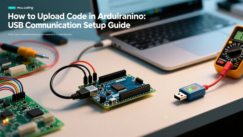
Understanding how to upload code in Arduino requires looking past the simple 'Upload' button in the IDE. At its core, uploading is a serial communication negotiation between your host computer and the microcontroller's bootloader via a USB-to-UART bridge. When you initiate an upload, the IDE compiles your C++ sketch into a HEX binary, opens a serial port connection at a specific baud rate (typically 115200 bps for modern boards, or 57600/19200 bps for older bootloaders), and triggers a hardware reset.
This reset is crucial. It forces the microcontroller to enter its bootloader state—a small, pre-flashed program residing in a protected section of the flash memory. The bootloader listens for a specific synchronization byte sequence from the IDE (via the AVRDUDE or BOSSA upload protocols). If the handshake succeeds, the bootloader receives the binary packets, writes them to the application flash memory, verifies the checksums, and finally jumps to the start address of your new sketch.
USB-to-Serial ICs: What is Actually on Your Board?
The physical communication layer depends entirely on the USB-to-Serial converter chip populated on your specific board. In 2026, the market is dominated by three primary ICs, each with distinct driver requirements and communication quirks.
| USB-UART IC | Common Boards | Driver Requirement (Win 11/macOS) | Approx. Clone Cost | Max Reliable Baud |
|---|---|---|---|---|
| ATmega16U2 | Genuine Uno R3, Mega 2560 | Native CDC-ACM (No driver needed) | $22.00 - $27.00 | 2,000,000 bps |
| CH340G / CH340C | Most Uno/Nano Clones | Requires WCH CH341SER driver | $4.50 - $8.00 | 921,600 bps |
| CP2102N | NodeMCU, ESP32 DevKit | Silicon Labs CP210x VCP Driver | $6.00 - $10.00 | 3,000,000 bps |
If you are using a clone board with a CH340 chip and your IDE port menu is greyed out, you are almost certainly missing the WCH driver. Always download the latest signed drivers directly from the manufacturer's site rather than relying on third-party driver aggregators, which often bundle outdated 2018-era binaries that fail Windows 11 Core Isolation memory integrity checks.
Step-by-Step: Configuring the Communication Port
To ensure a stable data pipe between your PC and the microcontroller, follow this exact configuration sequence in Arduino IDE 2.3.x:
- Physical Connection: Plug the Arduino directly into a motherboard USB port (rear I/O on desktops). Front panel hubs and unpowered USB docking stations often suffer from voltage droop on the 5V VBUS line, causing the serial IC to brownout during the high-current flash write cycle.
- Board & Port Selection: Navigate to Tools > Board and select your exact model. Then, go to Tools > Port. If you see multiple COM ports, unplug the Arduino, note which port disappears, plug it back in, and select that specific port.
- Programmer Setting: For standard USB uploads, the Tools > Programmer setting is actually ignored. It only matters if you are using an external hardware programmer (like a USBasp). Leave it on 'AVR ISP' or 'Atmel STK500' as a default.
- Initiate Upload: Click the right-facing arrow icon. Watch the console output at the bottom of the IDE. You should see the RX/TX LEDs on the board flicker rapidly in short bursts—this is the bootloader handshake and packet acknowledgment phase.
Troubleshooting: When the Handshake Fails
Serial communication is susceptible to noise, timing issues, and hardware faults. Here is how to resolve the most stubborn upload failures.
Edge Case 1: 'Programmer is not responding' or 'Timeout'
This error means the IDE sent the synchronization bytes, but the bootloader never replied. On custom or clone boards, the auto-reset circuit (which uses a 0.1µF capacitor between the DTR line and the RESET pin) may be missing or defective.
The Manual Reset Timing Trick:
Click 'Upload' in the IDE. Wait and watch the black console window. The exact moment the text 'Done compiling' (or the memory usage percentage) appears, immediately press and release the physical RESET button on the Arduino. You have roughly a 400-millisecond window before the bootloader times out and jumps to the existing user application. This manually triggers the bootloader to listen for the IDE's handshake.
Edge Case 2: Port Greyed Out or 'Board at X is not available'
If the port vanishes immediately after plugging in the board, you are likely using a 'charge-only' USB cable. These cables lack the D+ and D- data lines. Use a multimeter in continuity mode to verify the four internal pins of your USB-A to USB-B/Mini cable. Furthermore, if you are on a Linux distribution (like Ubuntu 24.04), non-root users are blocked from accessing serial ports by default. You must add your user to the dialout group via the terminal:
sudo usermod -a -G dialout $USER
Alternatively, create a custom udev rule in /etc/udev/rules.d/99-arduino.rules containing: SUBSYSTEM=='tty', ATTRS{idVendor}=='2341', MODE='0666' to grant permanent read/write permissions to the Arduino vendor ID.
Edge Case 3: Upload Interrupts at 40% with 'Verify Error'
If the upload starts but fails midway with a verification or checksum mismatch, the flash memory on the ATmega328P may be degrading, or the USB cable is suffering from EMI (Electromagnetic Interference). Move the cable away from switching power supplies and AC relays. If the issue persists on a known-good cable, the microcontroller's flash cells are likely worn out from excessive write cycles, requiring a chip replacement or an external ISP flash.
Advanced: Bypassing UART with ICSP
If you have completely bricked the bootloader (e.g., by setting incorrect fuse bits or uploading a sketch that immediately crashes and blocks serial interrupts), standard USB uploading will fail permanently. In this scenario, you must bypass the USB-UART communication entirely and use In-System Programming (ICSP).
Using a dedicated programmer like the official Arduino ISP or a Pololu USB AVR Programmer v2.1 (retailing around $15.00), connect the 6-pin SPI header (MISO, MOSI, SCK, RESET, 5V, GND) directly to your board. In the IDE, select your programmer under Tools > Programmer and use Sketch > Upload Using Programmer. This directly writes to the flash memory via the SPI protocol, ignoring the bootloader completely. Note that this process erases the bootloader, so you must subsequently use Tools > Burn Bootloader to restore standard USB upload functionality.
Frequently Asked Questions
Why do my RX/TX LEDs blink when I open the Serial Monitor but not during upload?
The Serial Monitor opens a standard UART data stream at your defined baud rate (e.g., 9600). The upload process uses a separate, high-speed bootloader handshake (115200 bps) and toggles the DTR line to reset the chip. If your board has separate hardware UARTs (like the Arduino Mega 2560), the upload uses UART0, while your sketch might be printing to UART1, resulting in different LED behaviors.
Can I upload code over Bluetooth or WiFi instead of USB?
Yes, but not natively through the standard IDE upload button without configuration. Boards with ESP32 or ESP8266 support Over-The-Air (OTA) updates via WiFi using the ArduinoOTA library. For classic AVR boards (Uno/Nano), you can use a Bluetooth HC-05 module wired to the TX/RX pins, paired as a virtual COM port on Windows, though you will almost certainly need to use the manual reset timing trick mentioned above, as the DTR auto-reset line does not transmit over standard Bluetooth SPP profiles.