
The Silent Killer: 5V to 3.3V Logic Level Mismatches
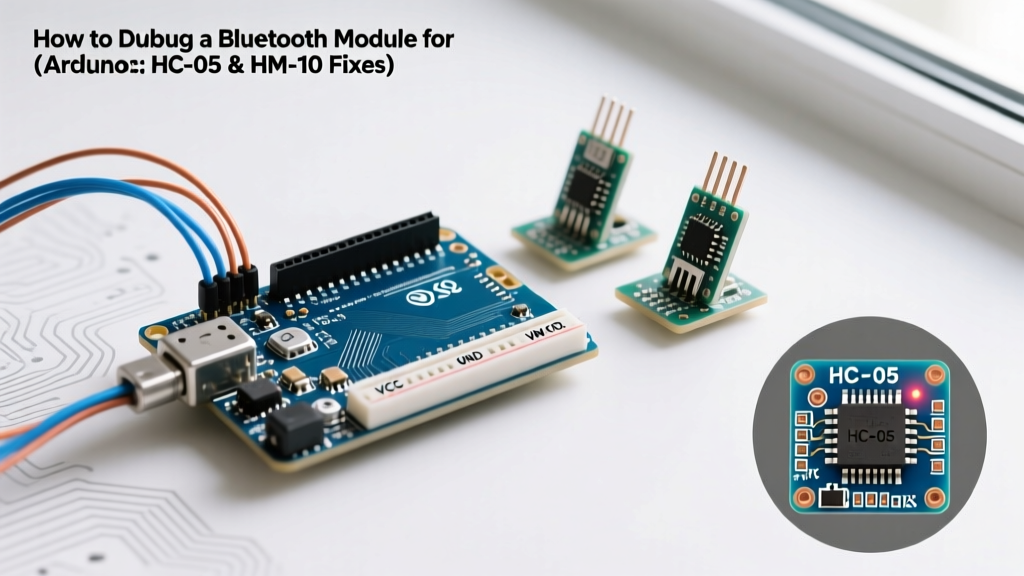
When integrating a bluetooth module for Arduino, the most common point of failure isn't in your code—it is in the silicon voltage tolerance. Most classic Arduino boards (Uno R3, Nano, Mega 2560) operate on 5V logic. However, nearly all modern Bluetooth modules, including the ubiquitous HC-05, HC-06, and BLE-based HM-10, operate on 3.3V logic.
Feeding a 5V TX signal from an ATmega328P directly into the 3.3V RX pin of an HC-05 module violates the absolute maximum ratings of the module's internal UART transceiver. While some modules have marginal overvoltage tolerance and might work for a few days, this mismatch causes silent packet loss, corrupted AT command responses, and eventual permanent silicon degradation. According to SparkFun's guide on logic levels, exceeding the Vcc by more than 0.5V on a CMOS input can trigger latch-up conditions, leading to erratic behavior that mimics software bugs.
The Voltage Divider Fix
To properly debug and operate your module, you must step down the Arduino's TX line. The most reliable, low-cost method is a resistive voltage divider. Using a 1kΩ and a 2kΩ resistor yields a safe 3.33V logic high.
- Wiring: Arduino Pin 11 (TX) → 1kΩ Resistor → HC-05 RX Pin.
- Grounding: 2kΩ Resistor from HC-05 RX Pin to common GND.
- Reverse Line: The HC-05 TX pin outputs 3.3V, which the Arduino's 5V logic safely reads as a HIGH (anything above 2.5V is recognized as HIGH by the ATmega328P). Connect HC-05 TX directly to Arduino Pin 10 (RX).
Power Brownouts: The 50mA Pairing Spike
If your Bluetooth module pairs successfully but disconnects the moment data transmission begins, or if it fails to appear on your smartphone's discovery list, you are likely experiencing a power brownout. During the initial RF discovery and pairing handshake, Bluetooth modules can draw current spikes of 30mA to 50mA.
Many hobbyists attempt to power the HC-05 VCC pin directly from the Arduino's onboard 3.3V regulator. On a standard Uno clone, this regulator is often an LP2985 rated for 150mA, but it is already burdened by the main microcontroller and any attached sensors. When the BT module spikes to 50mA, the regulator's voltage drops below the module's 3.0V minimum operating threshold, triggering an internal hardware reset.
Expert Troubleshooting Tip: Power your Bluetooth module from the Arduino's 5V pin, but use a dedicated AMS1117-3.3 LDO voltage regulator on your breadboard to step it down to a clean 3.3V. Alternatively, if your module has a 5V input pin (common on HC-05 breakout boards with an onboard regulator), ensure your USB power supply can deliver at least 1A to prevent main-rail sag.
SoftwareSerial Bottlenecks and Interrupt Collisions
When debugging a bluetooth module for Arduino, developers frequently rely on the SoftwareSerial library to free up pins 0 and 1 for the Serial Monitor. However, SoftwareSerial on 8-bit AVR microcontrollers is highly inefficient. It works by disabling global interrupts while bit-banging the UART signal. If your module is set to a baud rate higher than 19200, or if you have other interrupt-driven peripherals (like rotary encoders or IR receivers), SoftwareSerial will drop characters.
As noted in the official Arduino SoftwareSerial documentation, the library cannot transmit and receive simultaneously, and it struggles with timing accuracy at 38400 baud. If you are trying to send AT commands to an HC-05 (which defaults to 38400 baud in AT mode), SoftwareSerial will almost certainly corrupt the handshake.
The Hardware Serial Swap
To isolate whether your issue is software timing or hardware failure, swap to Hardware Serial (pins 0 and 1). Disconnect the module, upload your code, open the Serial Monitor, and verify your logic. Then, wire the module to pins 0 and 1. Warning: Always disconnect the TX/RX lines when uploading new sketches via USB, as the ATmega16U2 USB-to-Serial chip will conflict with the Bluetooth module.
AT Command State Machine Traps
Configuring a Bluetooth module requires sending specific AT commands. A massive source of frustration is the hidden state machine requirements for entering and exiting AT mode.
HC-05 (Classic Bluetooth)
The HC-05 has two distinct baud rates: 9600 for data mode, and 38400 for AT command mode. To enter AT mode, you must hold the module's EN (or KEY) pin HIGH before applying power to VCC. If you apply power first and then pull EN high, the module will ignore the state change. Furthermore, HC-05 AT commands require both a Carriage Return and a Line Feed (\r\n). If your Serial Monitor is set to 'No Line Ending', the module will buffer your commands indefinitely and never respond.
HM-10 (Bluetooth Low Energy)
The HM-10 operates at 9600 baud for both data and AT modes. However, many cheap HM-10 clones (often based on the CC2541 chip but running custom firmware) do not require \r\n and will actually reject the carriage return, returning an ERROR string. When debugging an HM-10, test with 'No Line Ending' first, then 'Carriage Return', and finally 'Both NL & CR' to determine the exact firmware flavor of your clone.
Bluetooth Module Debugging Matrix (2026 Landscape)
Choosing the right module dictates your debugging strategy. While classic modules are cheap, the 2026 landscape heavily favors BLE and integrated SoCs for new designs due to smartphone OS restrictions on classic Bluetooth serial profiles (SPP).
| Module | Protocol | Default Baud | Logic Level | Common Failure Mode |
|---|---|---|---|---|
| HC-05 | Classic SPP | 9600 (Data) / 38400 (AT) | 3.3V | EN pin timing missed; 5V logic frying RX. |
| HC-06 | Classic SPP | 9600 (Always) | 3.3V | No AT mode hardware trigger; requires specific firmware flash to change baud. |
| HM-10 | BLE 4.0 | 9600 | 3.3V | iOS blocks SPP; requires custom BLE UART app to test data flow. |
| ESP32-C3 | BLE 5.0 / WiFi | 115200 | 3.3V | Antenna trace detuning if placed near metal breadboards; requires ESP-IDF or Arduino core BLE library. |
Note: For new projects in 2026, bypassing external modules and using an ESP32-C3 ($3.50 average) provides native BLE 5.0, eliminating UART wiring bugs entirely. Refer to the Espressif Bluetooth API documentation for native stack debugging.
The FTDI Isolation Test: Bypassing the MCU
If you have verified your voltage divider, confirmed your power supply can handle 50mA spikes, and validated your baud rates, but the module still refuses to pair or echo data, you must isolate the module from the Arduino entirely.
Use a USB-to-TTL FTDI adapter (like the FT232RL breakout, typically $6-$8). These adapters allow you to select 3.3V or 5V logic via a physical jumper.
- Set the FTDI adapter to 3.3V logic.
- Connect FTDI TX to Module RX (no voltage divider needed since both are 3.3V).
- Connect FTDI RX to Module TX.
- Connect common GND and 3.3V VCC.
- Open a terminal program on your PC (like PuTTY or CoolTerm) at the correct baud rate.
If the module responds to AT commands or echoes data via the FTDI adapter but fails with the Arduino, your issue is strictly within the Arduino's code, pin mapping, or interrupt conflicts. If it fails on the FTDI adapter, the Bluetooth module's RF frontend or internal flash is likely dead—a common occurrence with sub-$3 clone modules subjected to static discharge.
Step-by-Step Diagnostic Flow
When faced with a non-responsive Bluetooth module, follow this strict triage sequence to avoid wasting hours on code when the issue is physical:
- Visual & Thermal Check: Power the module. Touch the main IC. If it is burning hot immediately, you have likely reversed VCC/GND or fed 5V into a 3.3V pin without a regulator.
- LED State Analysis: An HC-05 blinking rapidly (2x per second) is in discovery mode. Blinking slowly (1x every 2 seconds) means it is paired. Solid ON means connected and data link established. If the LED is off, check your ground connection.
- Loopback Test: Disconnect the module from the MCU. Connect the module's TX directly to its RX. Power it up and type on your phone's Bluetooth terminal app. If you see your keystrokes echoed back, the RF and UART layers are perfectly healthy.
- Code Verification: Upload a bare-minimum Hardware Serial bridge sketch. Ensure
Serial.begin()matches the module's exact baud rate.
By systematically eliminating hardware voltage faults, power delivery sags, and software timing collisions, you can transform the debugging process from a guessing game into a precise, repeatable engineering workflow.