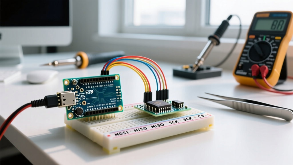

The Silent Failure of SPI Communication
When building sensor networks or high-speed data loggers, the Serial Peripheral Interface (SPI) is the go-to protocol for its raw speed and full-duplex capabilities. However, unlike I2C, SPI lacks a built-in hardware acknowledgment (ACK/NACK) mechanism. When an SPI Arduino setup fails, it rarely throws a visible error; instead, it fails silently, returning garbage data, endless 0xFF bytes, or flatlining at 0x00.
Troubleshooting these silent failures requires a systematic approach spanning physical layer signal integrity, logic level translation, and precise register configuration. According to the SparkFun SPI Tutorial, SPI relies on four main lines: MOSI, MISO, SCK, and CS. A fault in any single line breaks the entire transaction. Below is a comprehensive, expert-level guide to debugging your SPI bus.
Hardware Troubleshooting Matrix
Before diving into code, you must rule out physical layer faults. Use this diagnostic matrix to map your serial monitor output to specific hardware root causes.
| Serial Monitor Symptom | Probable Root Cause | Hardware Verification Step |
|---|---|---|
All reads return 0xFF |
MISO line disconnected, or slave sensor is unpowered. | Measure voltage at the sensor's VCC pin. Check MISO continuity with a multimeter. |
All reads return 0x00 |
MISO shorted to GND, or wrong CS pin is asserted. | Verify CS pin mapping. Ensure no stray solder bridges on the MISO header. |
| Intermittent garbage data | SCK ringing due to long wires, or logic level threshold mismatch. | Inspect wire length. Add 33Ω series termination resistors on MOSI/SCK. |
| Works on breadboard, fails in enclosure | Ground bounce or marginal 3.3V/5V logic thresholds. | Implement a dedicated ground plane or use a BSS138 level shifter. |
First byte correct, rest are 0x00 |
CS pin toggling too fast or missing SPI clock cycles. | Add a 10µs delay after pulling CS LOW before starting the clock. |
The Logic Level Trap: 5V vs 3.3V
One of the most common pitfalls in modern microcontroller projects is mixing 5V and 3.3V logic. The classic Arduino Uno R3 operates at 5V, while the vast majority of modern SPI peripherals (like the BME280 environmental sensor, W25Q128 SPI flash, or LSM6DS3 IMU) are strictly 3.3V devices.
Why Direct Connection Fails
Feeding 5V from the Arduino's MOSI or SCK pins directly into a 3.3V sensor can degrade or destroy the sensor's internal ESD protection diodes over time. Conversely, when the 3.3V sensor replies on the MISO line, its output high voltage (VOH) is typically around 3.0V to 3.3V. The ATmega328P on the Uno R3 requires an input high voltage (VIH) of at least 3.0V (0.6 × VCC). While 3.3V technically crosses this threshold, it leaves zero noise margin. Any slight voltage drop or ground bounce will cause the Arduino to misread a logic HIGH as a LOW.
The Proper Fix: BSS138 Level Shifters
Avoid using the TXS0108E level shifter for SPI. The TXS0108E features internal pull-up resistors and one-shot edge accelerators that often interfere with high-speed SPI clock edges, causing severe signal distortion. Instead, use a BSS138 MOSFET-based bi-directional level shifter (typically $2 to $4 for a 4-channel board). The BSS138 handles the capacitance of SPI lines much more gracefully and supports clock speeds well past 10 MHz without edge degradation.
Mastering SPI Modes: CPOL and CPHA
SPI is not a single standard; it is a collection of variations defined by Clock Polarity (CPOL) and Clock Phase (CPHA). As detailed in the All About Circuits SPI Guide, these two parameters create four distinct SPI modes (0 through 3).
- Mode 0 (CPOL=0, CPHA=0): Clock idles LOW. Data is sampled on the rising edge. (Standard for most SD cards and flash memory).
- Mode 1 (CPOL=0, CPHA=1): Clock idles LOW. Data is sampled on the falling edge.
- Mode 2 (CPOL=1, CPHA=0): Clock idles HIGH. Data is sampled on the falling edge.
- Mode 3 (CPOL=1, CPHA=1): Clock idles HIGH. Data is sampled on the rising edge. (Common in Maxim thermocouple ICs like the MAX31855).
If your Arduino is configured for Mode 0, but your sensor requires Mode 3, the data will be shifted by exactly one bit, resulting in completely unrecognizable hex values. Always consult the peripheral's datasheet timing diagram to verify the required mode.
Implementing Transactional SPI in Code
Legacy Arduino code often uses SPI.setClockDivider() and SPI.setDataMode(). This is deprecated and dangerous if you are using multiple SPI devices on the same bus that require different speeds or modes. The modern, robust approach uses SPI.beginTransaction() and SPISettings, as outlined in the official Arduino SPI Reference.
#include <SPI.h>

const int csPin = 10;
// Define settings: 4MHz, MSB first, SPI Mode 3
SPISettings mySensorSettings(4000000, MSBFIRST, SPI_MODE3);

void setup() {
  Serial.begin(115200);
  pinMode(csPin, OUTPUT);
  digitalWrite(csPin, HIGH); // Deselect slave immediately
  SPI.begin();
}

void loop() {
  SPI.beginTransaction(mySensorSettings);
  digitalWrite(csPin, LOW);

  // Perform SPI transfer
  byte response = SPI.transfer(0x80); // Example read command

  digitalWrite(csPin, HIGH);
  SPI.endTransaction();

  Serial.println(response, HEX);
  delay(1000);
}
Chip Select (CS) Edge Cases
The Chip Select (or Slave Select) line is active-LOW. A frequent mistake is failing to initialize the CS pin correctly before calling SPI.begin(). If the CS pin is left in its default high-impedance (INPUT) state during boot, ambient electrical noise can accidentally trigger the slave device, causing it to drive the MISO line and collide with other SPI traffic on the bus.
Pro Tip: Always set your CS pin toOUTPUTand drive itHIGHbefore you callSPI.begin(). Furthermore, if you are using a custom PCB, add a 10kΩ pull-up resistor on the CS line to ensure it remains HIGH during MCU reset sequences.
Signal Integrity: Wire Length and Capacitance
SPI was designed for on-board communication, typically spanning less than 10 centimeters. When makers use 30cm Dupont jumper wires to connect an Arduino to an SPI display or an Ethernet module (like the W5500), the parasitic capacitance of the wires acts as a low-pass filter. This rounds off the sharp square-wave edges of the SCK signal, eventually causing the slave device to miss clock pulses entirely.
If you must run SPI over distances greater than 15cm, you have three options:
- Reduce Clock Speed: Drop the SPI frequency from 8 MHz down to 1 MHz or 500 kHz using
SPISettings. - Add Series Termination: Solder a 33Ω to 100Ω resistor directly at the Arduino's SCK and MOSI output pins to dampen reflections and ringing.
- Use Differential Line Drivers: For runs over 1 meter, use RS-422 differential transceivers to convert the single-ended SPI signals into noise-immune differential pairs.
Validating with a Logic Analyzer
When the serial monitor gives you nothing but 0xFF, it is time to look at the raw waveforms. You do not need a $400 Saleae Logic Pro 8 to debug SPI. A generic 8-channel USB logic analyzer (based on the Cypress CY7C68013A chip) costs around $12 to $15 online and is more than sufficient for SPI debugging.
Download the open-source PulseView (Sigrok) software. Connect your logic analyzer probes to MOSI, MISO, SCK, and CS. In PulseView, add the 'SPI' protocol decoder, assign the channels, and set the correct CPOL/CPHA mode. PulseView will decode the raw hex bytes in real-time, allowing you to instantly verify if the Arduino is sending the correct register addresses, and exactly what the slave is replying with on the MISO line. This visual confirmation eliminates all guesswork from your SPI Arduino troubleshooting workflow.
Summary Checklist for SPI Success
- Verify 3.3V vs 5V logic levels and use BSS138 shifters if necessary.
- Confirm the exact SPI Mode (0-3) from the sensor's datasheet timing diagram.
- Use
SPI.beginTransaction()to protect against multi-device bus conflicts. - Initialize CS pins as OUTPUT and HIGH before
SPI.begin(). - Keep SCK wires under 15cm, or drop the clock speed for longer runs.
- Use a $15 logic analyzer and PulseView to decode the physical layer.