
The Modern Era of Microcontroller Development
Learning how to Arduino programming has evolved significantly over the last few years. While the classic 8-bit AVR architecture laid the groundwork for the maker movement, the landscape in 2026 is dominated by 32-bit ARM Cortex-M4 processors and Wi-Fi/BLE-enabled SoCs. The Arduino UNO R4 Minima, priced around $19.90, has largely replaced the legacy Uno R3 as the standard educational and prototyping board. This shift means that understanding modern memory management, higher-resolution ADCs, and non-blocking code execution is no longer optional—it is essential for writing robust firmware.
In this comprehensive walkthrough, we will bypass superficial blink tutorials and dive straight into a practical, scalable approach to Arduino C++ programming. We will configure the environment, write a precision PWM fading sketch utilizing the R4's 12-bit DAC capabilities, and explore professional debugging techniques.
Configuring the Arduino IDE 2.3 Environment
Before writing code, your development environment must be optimized. The Arduino IDE 2.3.x series introduces native autocomplete, real-time syntax checking, and an integrated Serial Plotter that are critical for rapid iteration.
- Download and Install: Grab the latest IDE from the official Arduino software page.
- Board Manager Integration: Navigate to Tools > Board > Boards Manager. Search for
Arduino UNO R4 Boardsand install the latest Renesas architecture package. - Port Selection: Connect your board via a high-quality USB-C data cable. Select the correct COM port (Windows) or
/dev/cu.usbmodem(macOS/Linux). If the port is greyed out, you are likely using a charge-only cable or lack the necessary CH340/RA4M1 USB drivers.
Core Architecture: The Setup and Loop Paradigm
Every Arduino sketch relies on two foundational functions. Understanding their execution context is the first step in mastering how to Arduino programming effectively.
setup(): Executes exactly once upon power-up or hardware reset. This is where you initialize pin modes, start serial communication, and configure peripheral libraries (like I2C or SPI).loop(): Runs continuously in an infinite while-loop managed by the underlying RTOS or bare-metal HAL. This is where your main application logic resides.
Expert Insight: Never place blocking delays or heavy computational tasks inside
setup()that rely on external hardware states unless you implement robust timeout mechanisms. A hung I2C sensor during setup will brick the boot sequence until the hardware fault is cleared.
Walkthrough: Precision PWM LED Fading on the UNO R4
To demonstrate modern Arduino programming, we will build a smooth LED fading circuit. Unlike the legacy 8-bit Uno R3, which was limited to 8-bit PWM (0-255), the UNO R4 Minima features a 12-bit DAC and supports 12-bit PWM resolution (0-4095), allowing for buttery-smooth transitions without visible stepping.
Hardware Configuration
You will need the following components:
- 1x Arduino UNO R4 Minima
- 1x Standard 5mm LED (Forward voltage ~2.1V)
- 1x 220Ω Through-hole Resistor (1/4W)
- 2x Jumper wires
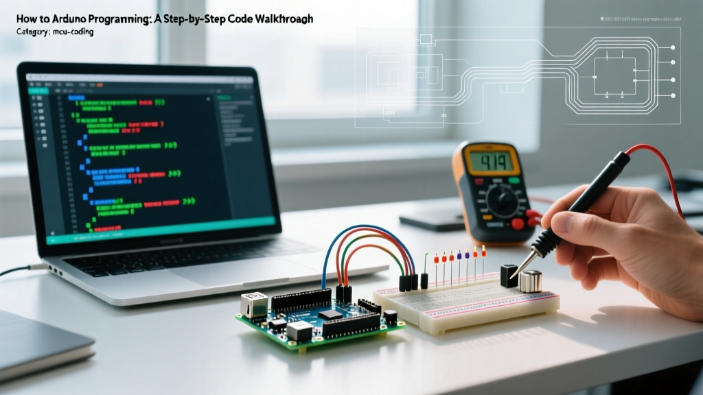
Wiring: Connect Pin 9 on the Arduino to the anode (long leg) of the LED. Connect the cathode (short leg) to one end of the 220Ω resistor, and the other end of the resistor to the GND pin. Pin 9 is hardware-PWM capable, indicated by the tilde (~) symbol on the silkscreen.
The C++ Implementation
Below is the optimized code leveraging the Arduino Language Reference standards for the RA4M1 architecture.
// Pin definition for hardware PWM
const int ledPin = 9;

// Variables for fading logic
int brightness = 0;
int fadeAmount = 16; // 4096 / 256 steps for smooth 12-bit fading

void setup() {
  // Initialize serial communication at 115200 baud for debugging
  Serial.begin(115200);
  while (!Serial) {
    ; // Wait for serial port to connect (Native USB)
  }

  // Set pin as output
  pinMode(ledPin, OUTPUT);

  // CRITICAL: Upgrade PWM resolution from default 8-bit to 12-bit
  analogWriteResolution(12);

  Serial.println("12-Bit PWM Fading Initialized.");
}

void loop() {
  // Apply the 12-bit brightness value (0 to 4095)
  analogWrite(ledPin, brightness);

  // Increment or decrement brightness
  brightness = brightness + fadeAmount;

  // Reverse the fade direction at the 12-bit boundaries
  if (brightness <= 0 || brightness >= 4095) {
    fadeAmount = -fadeAmount;
  }

  // Non-blocking delay using millis() instead of delay()
  static unsigned long lastUpdate = 0;
  if (millis() - lastUpdate >= 15) {
    lastUpdate = millis();
    // The actual update happens on the next loop iteration
  }
}
Hardware Comparison: Choosing Your Microcontroller
When learning how to Arduino programming, selecting the right hardware dictates your memory constraints and peripheral availability. Below is a 2026 comparison of the most common beginner-to-intermediate boards.
| Feature | Uno R3 (Legacy) | Uno R4 Minima | Nano ESP32 |
|---|---|---|---|
| MCU Core | 8-bit AVR (ATmega328P) | 32-bit ARM Cortex-M4 (RA4M1) | 32-bit Xtensa LX7 (ESP32-S3) |
| Clock Speed | 16 MHz | 48 MHz | 240 MHz (Dual Core) |
| Flash Memory | 32 KB | 256 KB | 16 MB (External) |
| SRAM | 2 KB | 32 KB | 512 KB |
| ADC Resolution | 10-bit | 14-bit | 12-bit |
| Approx. Price | $27.00 | $19.90 | $18.50 |
Advanced Debugging: Ditching the Delay() Function
The most common mistake beginners make when figuring out how to Arduino programming is relying on the delay() function. delay() is a blocking function; it halts the CPU, preventing the microcontroller from reading sensors, updating displays, or listening for network interrupts.
Instead, professional firmware engineers use a state-machine approach paired with the millis() timer. The millis() function returns the number of milliseconds since the board began running the current program. By tracking the timestamp of the last event, you can execute code at precise intervals without blocking the main thread.
unsigned long previousMillis = 0;
const long interval = 1000; // 1 second interval

void loop() {
  unsigned long currentMillis = millis();

  if (currentMillis - previousMillis >= interval) {
    previousMillis = currentMillis; // Save the last time you blinked

    // Perform non-blocking task here
    toggleLED();
  }

  // The CPU is free to perform other tasks here simultaneously
  readSensors();
  checkBluetooth();
}
Memory Management and Edge Cases
As your sketches grow, you will inevitably hit hardware limitations. Understanding the difference between Flash (program memory) and SRAM (dynamic memory) is vital.
- String Objects vs. Char Arrays: The Arduino
Stringclass is notorious for causing SRAM heap fragmentation, leading to random reboots on memory-constrained boards. Always prefer fixed-lengthchararrays or theF()macro to keep static strings in Flash memory. Example:Serial.println(F("This string stays in Flash")); - Floating Pins: If you configure a pin as
INPUTbut leave it physically unconnected, it will act as an antenna, picking up electromagnetic interference and causing erraticdigitalRead()values. Always useINPUT_PULLUPto engage the internal 20kΩ-50kΩ pull-up resistor unless an external pull-down is explicitly designed into your PCB. - Baud Rate Mismatches: If your Serial Monitor outputs garbled text (e.g.,
ÿÿÿ), your IDE baud rate does not match yourSerial.begin()declaration. Standardize on115200for modern USB-to-UART bridges, as the legacy9600baud is unnecessarily slow for high-frequency data logging.
Final Thoughts on Firmware Architecture
Mastering how to Arduino programming is less about memorizing syntax and more about understanding hardware constraints, timing, and electrical realities. By adopting 12-bit resolution where available, eliminating blocking delays, and respecting SRAM boundaries, you transition from a hobbyist copying tutorials to an embedded systems developer writing production-ready firmware. For further reading on architecture specifics, consult the Arduino UNO R4 Minima Cheat Sheet to map out your pin multiplexing before writing a single line of code.