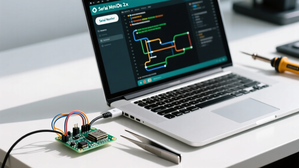

The Critical Role of the Serial Monitor in MCU Debugging
When developing firmware for microcontrollers, blind coding is a recipe for endless frustration. The Serial Monitor acts as your primary window into the brain of your Arduino, ESP32, or STM32 board, bridging the gap between raw UART (Universal Asynchronous Receiver-Transmitter) hardware and human-readable text. If you are searching for exactly how to open Arduino Serial Monitor, configure it for high-speed telemetry, or troubleshoot garbled output, this communication setup guide covers the modern 2026 workflow.
Whether you are flashing a legacy Arduino Uno R3 or a modern ESP32-S3 with native USB, mastering the Serial Monitor is non-negotiable for efficient embedded systems engineering.
Prerequisites for UART Communication
Before opening the software interface, your hardware communication pipeline must be correctly established. The Serial Monitor relies on a stable physical or virtual COM port connection.
Hardware & Driver Requirements
- Native USB Boards (Arduino Leonardo, ESP32-S3, RP2040): These boards emulate a serial port over USB using CDC (Communication Device Class). No external drivers are typically required on modern Windows 11, macOS, or Linux kernels.
- UART-to-USB Bridge Boards (Arduino Uno R3, Nano, Mega): These rely on dedicated bridge ICs. Genuine boards use the ATmega16U2, while cost-effective clones ($3 to $6 on Amazon) typically use the CH340G or CP2102. You must install the specific CH340 or CP210x VCP (Virtual COM Port) drivers to make the port visible to the IDE.
- Cabling: Always use a data-capable USB cable. A charge-only cable will power the board but will result in a greyed-out port menu.
Step-by-Step: How to Open Arduino Serial Monitor
The Arduino ecosystem has transitioned heavily toward the modernized IDE 2.x architecture, though legacy 1.8.x setups remain in industrial environments. Here is how to access the monitor across platforms.
Method 1: Arduino IDE 2.x (Current Standard)
- Connect your microcontroller via USB and verify the port is selected under Tools > Port.
- Ensure your sketch includes
Serial.begin(9600);(or your desired baud rate) inside thesetup()function. - Upload your sketch to the board.
- Click the Serial Monitor icon (a magnifying glass over a page) located in the top-right corner of the IDE toolbar.
- Alternatively, use the keyboard shortcut: Ctrl + Shift + M (Windows/Linux) or Cmd + Shift + M (macOS).
Method 2: Arduino IDE 1.8.x (Legacy)
- Connect and select your board and port.
- Navigate to the top menu bar and click Tools > Serial Monitor.
- Alternatively, click the magnifying glass icon in the top-right corner or use the Ctrl + Shift + M shortcut.
Pro-Tip for IDE 2.x Users: The modern IDE features a split-screen mode. You can keep the Serial Monitor docked at the bottom of the screen while editing code, eliminating the need to constantly close and reopen the window during iterative debugging.
Configuring the Monitor for Reliable Data Parsing
Simply knowing how to open Arduino Serial Monitor is only half the battle; configuring it to match your firmware's UART parameters is where most beginners fail.
Baud Rate Matching
The baud rate dictates the speed of data transmission in bits per second (bps). The rate declared in your firmware must exactly match the dropdown selection in the Serial Monitor. A mismatch results in garbled, unreadable characters (e.g., ÿÿÿ).
| Baud Rate | Standard Use Case | Max Reliable Distance (RS-232/TTL) | Notes |
|---|---|---|---|
| 9600 | Basic debugging, AT Commands | ~15 meters (TTL over RS-232) | Default for most legacy Arduino tutorials. |
| 115200 | ESP8266/ESP32 boot logs, fast telemetry | ~1-2 meters (Raw TTL) | Standard for Espressif chips and high-speed data. |
| 250000 | 3D Printer firmware (Marlin) | Very short runs | Requires high-quality shielded USB cables. |
| 31250 | MIDI over Serial | N/A (Opto-isolated) | Specific to musical instrument digital interfaces. |
Line Ending Configurations
When sending data from your computer to the Arduino (e.g., typing a command to toggle an LED), the Serial Monitor appends hidden characters based on your dropdown selection. According to SparkFun's Serial Communication Guide, misunderstanding these terminators causes endless Serial.parseInt() timeouts.
- No line ending: Sends exactly what you type. Best for raw byte streams.
- Newline (NL / \n): Appends an ASCII 10 (Line Feed). Standard for Linux-based parsing.
- Carriage return (CR / \r): Appends an ASCII 13. Common in older AT-command modems.
- Both NL & CR (\r\n): Appends ASCII 13 then ASCII 10. The standard for HTTP and Windows-based text protocols.
Real-World Troubleshooting & Edge Cases
Even when you know how to open Arduino Serial Monitor, hardware quirks can block communication. Here are specific failure modes and their solutions.
1. The "Port Greyed Out" or "Board at COMX not available" Error
If the port menu is disabled, the OS does not recognize the USB-to-UART bridge. Fix: Open your OS Device Manager (Windows) or System Report (macOS). If you see an "Unknown USB Device (Device Descriptor Request Failed)," your cable is likely charge-only, or the CH340 driver has crashed. Unplug the board, uninstall the hidden COM port in Device Manager, reinstall the CH340 VCP driver, and reconnect.
2. ESP32 Boot Pin Conflicts (GPIO 1 / TX0)
The ESP32 uses GPIO 1 (TX0) for Serial output. However, this pin is also sampled during boot to determine the flash mode. If your circuit pulls GPIO 1 LOW (e.g., via a voltage divider or an active-low sensor), the ESP32 will enter the serial bootloader and halt your sketch. Fix: Never use GPIO 1 for external components that pull the pin low. Refer to the Espressif UART API Guide for alternative pin mappings using the UART matrix.
3. The Serial Monitor Freezes the IDE
If your microcontroller is flooding the serial buffer with thousands of lines per second (e.g., logging raw ADC data in a tight loop() without delays), the IDE 2.x rendering engine may lock up. Fix: Implement a non-blocking timer using millis() to throttle your Serial.print() statements to a maximum of 30-50 updates per second.
Memory Optimization: The F() Macro
When using the Serial Monitor for extensive debugging, you can quickly exhaust the SRAM of an ATmega328P (which only has 2KB of SRAM). Standard Serial.print("Sensor value: "); commands copy the string into precious RAM at runtime.
To optimize memory, wrap your string literals in the F() macro:
Serial.println(F("Sensor value: "));
This forces the compiler to leave the string in Flash memory (PROGMEM), reading it byte-by-byte during transmission. This simple technique is a hallmark of professional embedded firmware and prevents mysterious heap-collision reboots in long-running deployments.
Advanced Alternatives to the Built-in Monitor
While the native IDE monitor is sufficient for 90% of tasks, complex communication setups require specialized terminal software. Consider these alternatives when the built-in tool falls short:
- Serial Plotter (Built-in): Accessed via Tools > Serial Plotter. Parses comma-separated integer/float data into real-time graphs. Essential for tuning PID loops and visualizing IMU sensor noise.
- PuTTY / TeraTerm: Ideal for raw SSH/Telnet and serial terminal emulation. Supports logging output directly to a .txt file for post-processing, which the Arduino IDE struggles with.
- CoolTerm: A cross-platform favorite for sending hex packets and binary files over serial, crucial when updating firmware via custom bootloaders.
Conclusion
Mastering how to open Arduino Serial Monitor and configuring its underlying UART parameters transforms it from a simple text window into a powerful diagnostic instrument. By matching baud rates, understanding line terminators, and respecting hardware pin constraints, you will drastically reduce your debugging time. For further reading on IDE 2.x features, consult the Official Arduino Serial Monitor Documentation.