
Why Your IR Receiver is Failing: Beyond the Basic Wiring
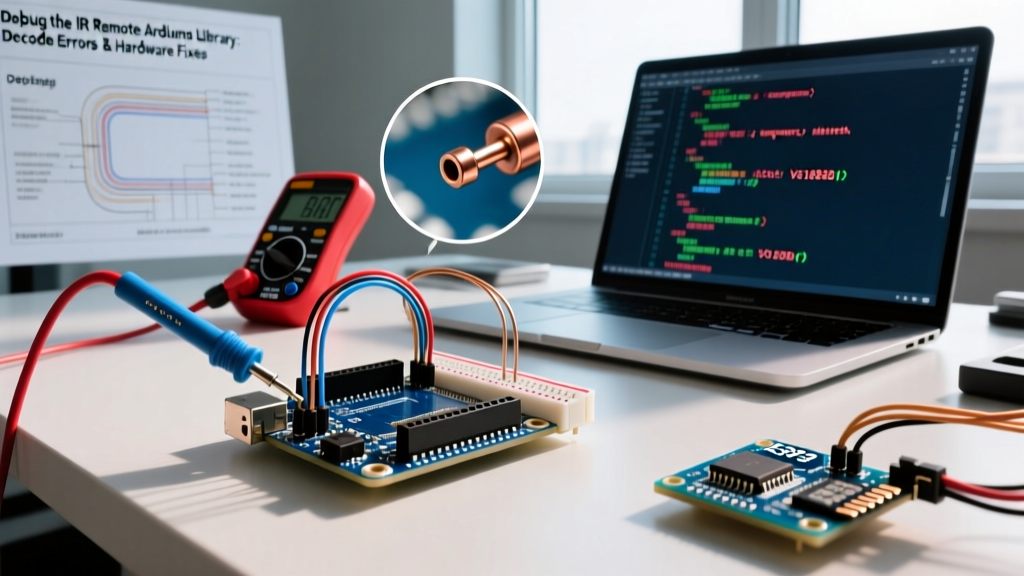
Integrating infrared communication into a microcontroller project seems trivial until your Arduino Nano starts outputting garbage hex codes, freezing, or completely ignoring your remote. The Arduino-IRremote library is the undisputed gold standard for decoding these signals, but hardware realities, cheap components, and software updates frequently derail projects. As of 2026, the landscape of IR debugging requires a deep understanding of both the 38kHz carrier demodulation hardware and the microcontroller's internal timer peripherals.
Critical Version Warning: If you are following tutorials written before 2022, they likely use the deprecatedirrecv.enableIRIn()syntax. Version 4.0+ of the library completely overhauled the API to support modern ESP32 and RP2040 architectures. You must now instantiate the receiver globally usingIRrecv IrReceiver(RECV_PIN)and initialize it in setup withIrReceiver.begin().
Diagnosing 'Ghost' Signals and AGC Desensitization
The most common failure mode in DIY IR projects is the 'ghost' signal—where the receiver triggers randomly without a remote, or fails to register a button press when room lights are on. This is almost always a hardware issue masquerading as a software bug.
The VS1838B vs. Vishay TSOP38238 Reality
Most starter kits include the VS1838B receiver. At $0.10 to $0.20 in bulk, it is cheap, but it lacks a robust internal Automatic Gain Control (AGC) circuit and proper EMI shielding. When exposed to modern LED room lighting or the 100Hz/120Hz flicker of CFL bulbs, the VS1838B's internal AGC maxes out its gain to compensate for the ambient noise floor, effectively blinding it to your remote's 38kHz signal.
The Fix: If your project operates in a well-lit room, upgrade to the Vishay TSOP38238 (typically $1.50 to $2.20 on Mouser or Digi-Key). Vishay's proprietary AGC algorithm specifically filters out continuous 100Hz/120Hz noise and DC light sources. If you must use the VS1838B, you need to stabilize the power rail.
The Mandatory RC Filter for Noisy Power Rails
USB buck converters and cheap linear regulators often introduce 20mV to 50mV of high-frequency ripple onto the 5V rail. The VS1838B interprets this ripple as IR data. You must implement a localized decoupling network directly at the receiver's VCC and GND pins:
- 100nF (0.1µF) Ceramic Capacitor: Placed as close to the VCC/GND pins as physically possible to shunt high-frequency switching noise.
- 47µF Electrolytic Capacitor: Placed in parallel to handle low-frequency voltage sags when the internal photodiode amplifier draws peak current during a signal burst.
- 100Ω Series Resistor: Place this between the main 5V rail and the receiver's VCC pin to form an RC low-pass filter with the 47µF capacitor.
Resolving Timer and Pin Conflicts
The IR remote Arduino library relies heavily on hardware timers to measure the microsecond durations of IR pulses (marks and spaces) without blocking the main loop(). If your project also uses PWM, tone generation, or specific communication protocols, you will encounter silent timer collisions.
| Microcontroller | Default IR Timer | Common Conflicts | Resolution / Workaround |
|---|---|---|---|
| ATmega328P (Uno/Nano) | Timer2 | tone() function, PWM on Pins 11 & 3 |
Use toneAC library (uses Timer1) or shift PWM to Pins 5, 6, 9, 10. |
| ATmega32U4 (Leonardo/Micro) | Timer1 | Servo library, PWM on Pins 9, 10 | Redefine IR_USE_TIMER3 in the library's boarddefs.h before compiling. |
| ESP32 (All Variants) | RMT Peripheral | LED strips (WS2812 via RMT), some I2S audio | Assign a dedicated, unused RMT channel (e.g., RMT_CHANNEL_2) in IrReceiver.begin(). |
Fixing Protocol Decode Failures and Timing Skew
According to the definitive San Bergers IR Protocol Knowledge Base, the NEC protocol expects a precise 9000µs header mark followed by a 4500µs space. The Arduino-IRremote library allows a default tolerance (usually 25%) to account for minor transmitter variances. However, if you are using a cheap Arduino Nano clone with a ceramic resonator instead of a quartz crystal, the microcontroller's internal clock may be skewed by 3% to 5%. This skew compounds across the 32-bit payload, causing the final checksum to fail and the library to return UNKNOWN.
Adjusting the Tolerance Macro
If your raw dumps show consistent timing skew (e.g., your 9000µs header is consistently reading as 8400µs), you can widen the library's acceptance window. Add the following definition before including the library in your sketch:
#define TOLERANCE 30
#include <IRremote.hpp>
This widens the acceptable timing variance to 30%, rescuing decodes from boards with poor oscillator accuracy or remotes with aging carbon contacts.
Advanced Debugging: Raw Dump Analysis
When the standard decoders (NEC, Sony, RC5, Samsung) fail, you must look at the raw microsecond data. The Adafruit IR Sensor Guide provides excellent baseline wiring, but for deep debugging, you need to bypass the protocol parsers entirely.
Use the raw formatted print function introduced in recent library versions to export the exact mark/space array:
if (IrReceiver.decode()) {
IrReceiver.printIRResultRawFormatted(&Serial, true);
IrReceiver.resume();
}
Reading the Raw Output
The serial monitor will output an array of integers representing microseconds. Remember that the receiver output is inverted: a 'Mark' (IR LED ON) pulls the receiver's data pin LOW, and a 'Space' (IR LED OFF) lets the pin float HIGH. The library handles this inversion internally, but if you are hooking a logic analyzer up to the raw photodiode output before the demodulator IC, the logic states will be reversed.
- Valid NEC Header: Look for
+9000, -4500. - Valid Sony 12-bit Header: Look for
+2400, -600. - Noise / Ghosting: You will see rapid, erratic microsecond spikes (e.g.,
+12, -8, +15, -10) that do not conform to any 38kHz carrier burst envelope. This confirms hardware EMI issues.
Carrier Frequency Mismatches (38kHz vs 56kHz)
Not all remotes use the standard 38kHz carrier frequency. While 38kHz dominates the consumer TV and audio market, specific HVAC systems, ceiling fans, and older Bang & Olufsen equipment utilize 36kHz, 40kHz, or even 56kHz carriers. A standard TSOP38238 receiver is bandpass-filtered specifically for 38kHz. If you attempt to decode a 56kHz remote with a 38kHz receiver, the internal demodulator will reject the carrier envelope entirely, resulting in zero output on the data pin.
Troubleshooting Step: If raw dumping yields absolutely nothing (not even noise), suspect a carrier mismatch. Swap your receiver for a TSOP34156 (56kHz) or a wide-bandwidth receiver like the TSOP4838, which has a slightly wider bandpass filter capable of catching 36kHz and 40kHz signals with only a minor reduction in reception range.