
The I2C Bottleneck: Why Your MCP23017 Isn't Talking
The Waveshare MCP23017 I/O Expansion Board remains one of the most cost-effective solutions in 2026 for adding 16 GPIO pins to microcontrollers like the Arduino Uno R4 Minima or ESP32-S3. Priced typically between $6.50 and $8.00, it is a staple in industrial control panels and DIY robotics. However, when developers search for the waveshare mcp23017 arduino library, they are often met with a mix of generic Adafruit forks, RobTillaart optimizations, and Waveshare's own legacy C++ snippets. While the software ecosystem is vast, 90% of initialization failures and bus lockups stem from a fundamental misunderstanding of the I2C physical layer and the MCP23017's internal register architecture.
This guide bypasses basic blink tutorials and dives directly into advanced debugging, hardware-software isolation, and interrupt handling for the Waveshare breakout board.
Hardware vs. Software: Isolating the Fault Domain
Before blaming the waveshare mcp23017 arduino library for a failed compilation or silent runtime error, you must isolate the I2C physical bus. The most common failure mode is a complete bus lockup, where the microcontroller's Wire.requestFrom() function hangs indefinitely.
Expert Diagnostic Rule: If your I2C scanner sketch hangs on the serial monitor rather than returning a "No device found" message, the issue is strictly hardware (missing pull-ups or bus capacitance). Software libraries cannot cause a physical I2C hang; they can only misinterpret the data.
To verify the hardware layer, upload a bare-metal I2C scanner sketch without any MCP23017 library includes. If the Waveshare board does not appear at its default 0x20 address, no library in the world will make it work until the physical layer is corrected.
Common Wire.endTransmission() Error Codes
When the hardware is partially functional but misconfigured, the Arduino Wire library returns specific error codes. Understanding these is critical for debugging the library's underlying I2C calls.
| Return Code | Meaning | MCP23017 Specific Failure Mode | Corrective Action |
|---|---|---|---|
| 0 | Success | Data acknowledged. | None. Proceed to register configuration. |
| 1 | Data too long for buffer | Library attempting to burst-write >32 bytes to the MCP23017 sequential registers. | Break the write operation into smaller chunks in your code. |
| 2 | NACK on address | Waveshare A0/A1/A2 jumpers mismatch the library's initialized hex address. | Verify physical jumper states against the 0x20-0x27 mapping. |
| 3 | NACK on data | Attempting to write to a read-only register (e.g., INTCAP or GPIO). | Ensure you are writing to OLAT (Output Latch) instead of GPIO. |
| 4 | Other error / Bus Lockup | SDA line held low by the MCP23017 due to an interrupted read cycle. | Implement a software I2C bus recovery sequence (see below). |
Addressing the A0, A1, A2 Jumper Confusion
The Waveshare MCP23017 breakout exposes the address configuration pins (A0, A1, A2). According to the Microchip MCP23017 Datasheet, the base I2C address is 0100000 (0x20). The state of these three pins modifies the last three bits.
- Default (Waveshare): A0=GND, A1=GND, A2=GND →
0x20 - Common Conflict: A0=VCC, A1=GND, A2=GND →
0x21 - Maximum Address: A0=VCC, A1=VCC, A2=VCC →
0x27
Edge Case Warning: Some older revisions of the Waveshare board use 0-ohm surface-mount resistors instead of solder jumpers or DIP switches. If your I2C scanner shows the device at 0x20 despite your attempts to change the jumper caps, inspect the PCB traces with a magnifying glass to ensure the resistors are actually bridging the VCC pads and not permanently tied to GND.
Interrupt Handling: The Silent Failure Mode
One of the primary reasons engineers choose the MCP23017 over shift registers is its dual interrupt pins (INTA and INTB). However, configuring interrupts via the waveshare mcp23017 arduino library often results in phantom triggers or missed events.
Step-by-Step Interrupt Configuration
- Mirror Interrupts (IOCON Register): By default, INTA is tied to Port A (GPA) and INTB to Port B (GPB). If you are routing both to a single microcontroller interrupt pin, you must set the
MIRRORbit in theIOCONregister to1. - Open-Drain Output (ODR Bit): If sharing the interrupt line with other I2C devices, set the
ODRbit inIOCONto1. This overrides the INTPOL bit and configures the INT pins as open-drain, requiring an external pull-up resistor. - Clear the Interrupt Flag: The MCP23017 will hold the INT pin active until the microcontroller reads the
INTCAP(Interrupt Capture) orGPIOregister. If your Arduino ISR (Interrupt Service Routine) does not read one of these registers, the interrupt will fire continuously, crashing your main loop.
// Example ISR for MCP23017 Interrupt
void handleMCPInterrupt() {
  // Read INTCAP to clear the interrupt flag on the chip
  uint16_t capturedState = mcp.readPort(INTCAP);
  // Set a volatile flag for the main loop to process
  interruptTriggered = true;
}
Pull-Up Resistor Dynamics on the Waveshare Breakout
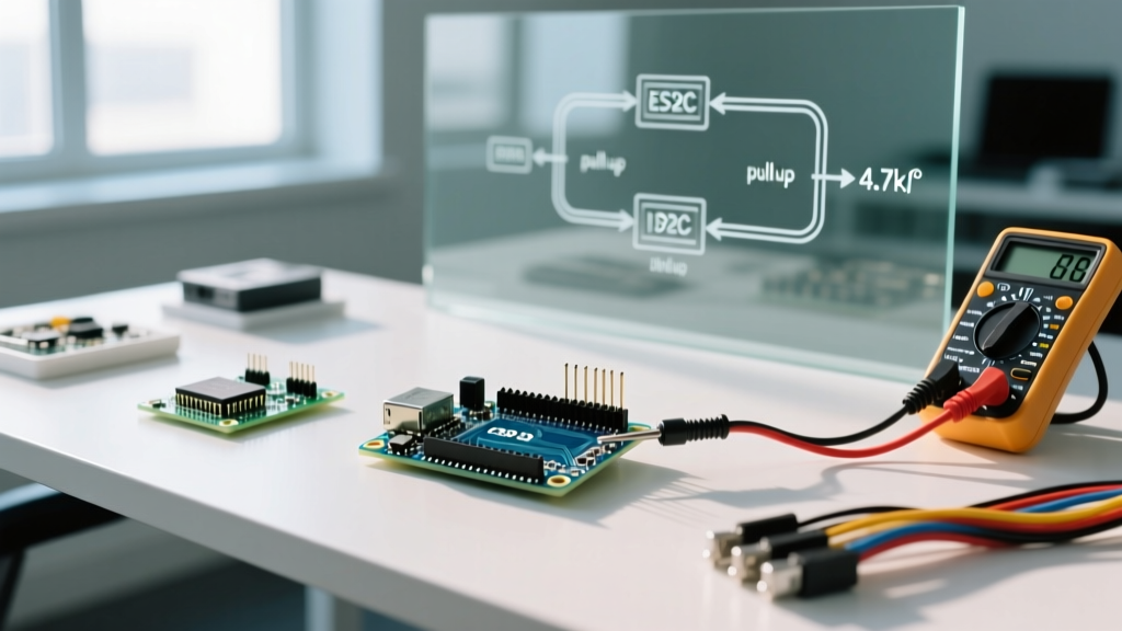
The most heavily debated topic in I2C design is pull-up resistor sizing. The NXP I2C Bus Specification dictates strict limits on bus capacitance and rise times. The Waveshare MCP23017 board is designed to be modular and does not include populated pull-up resistors on the SDA and SCL lines to prevent parallel resistance issues when daisy-chaining multiple modules.
If you are using an Arduino Uno R4 Minima or an ESP32-S3, relying on the microcontroller's internal pull-ups (typically 30kΩ to 45kΩ) is a critical mistake for Fast Mode (400kHz) I2C.
- Standard Mode (100kHz): Internal pull-ups might work if the I2C trace length is under 10cm.
- Fast Mode (400kHz): You must add external 4.7kΩ pull-up resistors to both SDA and SCL, tied to the logic voltage (3.3V or 5V). Without them, the RC rise time will exceed the 300ns maximum, causing the MCP23017 to misinterpret clock pulses, leading to random NACKs and corrupted register writes.
Advanced Debugging: Software I2C Bus Recovery
If your system experiences a brownout or a loose connection while the MCP23017 is transmitting a '0' bit, the expander will hold the SDA line low indefinitely. The Arduino Wire Library will hang on the next Wire.beginTransmission() call because the hardware I2C peripheral waits for a STOP condition that can never occur.
To build robust field-deployable code, implement a software bus recovery routine before initializing your MCP23017 library:
void recoverI2CBus() {
  // Disconnect hardware I2C peripheral
  Wire.end();

  // Manually toggle SCL to release SDA
  pinMode(SCL_PIN, OUTPUT);
  for (int i = 0; i < 9; i++) {
    digitalWrite(SCL_PIN, LOW);
    delayMicroseconds(5);
    digitalWrite(SCL_PIN, HIGH);
    delayMicroseconds(5);
  }

  // Generate a manual STOP condition
  pinMode(SDA_PIN, OUTPUT);
  digitalWrite(SDA_PIN, LOW);
  delayMicroseconds(5);
  digitalWrite(SCL_PIN, HIGH);
  delayMicroseconds(5);
  digitalWrite(SDA_PIN, HIGH);

  // Re-initialize hardware I2C
  Wire.begin();
}
Summary Checklist for Field Deployments
Before sealing your enclosure and deploying your Waveshare MCP23017 project into a production environment, verify the following parameters:
- Logic Levels: Ensure the VCC supplied to the Waveshare board matches the microcontroller's I2C logic levels. Supplying 5V to the MCP23017 while using a 3.3V ESP32 without a level shifter will degrade the ESP32's GPIO pins over time.
- Decoupling Capacitor: The Waveshare board includes a 100nF decoupling capacitor, but if you are driving high-current loads (like relays) directly from the GPIO pins, add a secondary 10μF bulk capacitor near the board's VCC/GND header to prevent I2C brownouts.
- Library Selection: For high-speed polling, bypass the standard object-oriented wrappers and use direct
Wire.write()commands to theGPIOAandGPIOBregisters (0x12 and 0x13) to minimize I2C overhead. - Sequential Mode: Verify the
SEQOPbit in theIOCONregister. If disabled, reading multiple bytes will return the same register repeatedly. Enable it for sequential port reads.
Mastering the waveshare mcp23017 arduino library requires looking past the software API and respecting the electrical realities of the I2C bus. By systematically addressing pull-up deficiencies, interrupt flag clearing, and bus lockup recovery, you can transform this $7 breakout board into a bulletproof industrial I/O solution.