
Beyond the RC522: Why Advanced RFID Demands Better Hardware
Most introductory tutorials for RFID tag reader Arduino projects stop at the MFRC522 module. While the RC522 is excellent for learning basic 13.56 MHz SPI communication and reading legacy MIFARE Classic tags, it completely falls short for modern, high-throughput, or secure applications. In 2026, commercial inventory systems, secure access gates, and advanced IoT deployments require Ultra-High Frequency (UHF) for bulk reading and secure High Frequency (HF) for cryptographic authentication.
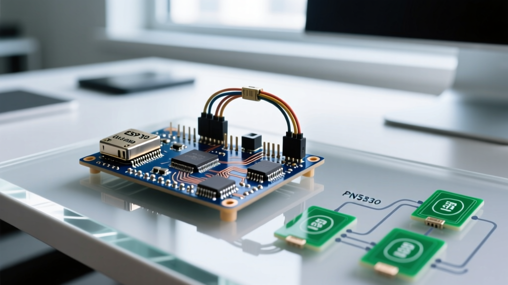
Transitioning from basic hobbyist modules to industrial-grade reader chips like the Impinj Indy R2000 (UHF) or the NXP PN532 (HF/NFC) introduces complex engineering challenges. These include SPI bus contention, RF impedance matching, and implementing the EPC Gen2 slotted ALOHA anti-collision algorithm. This guide explores advanced integration techniques using the ESP32-S3 as the primary microcontroller, leveraging its dual-core architecture to handle high-speed SPI data streams without blocking WiFi or Bluetooth operations.
Hardware Matrix: UHF R2000 vs. HF PN532 for ESP32/Arduino
Selecting the correct reader IC depends entirely on your physical layer requirements. UHF provides range and speed, while HF provides near-field security and smartphone interoperability.
| Feature | MFRC522 (Basic) | NXP PN532 (Advanced HF) | Impinj Indy R2000 (UHF) |
|---|---|---|---|
| Frequency | 13.56 MHz | 13.56 MHz | 860 - 960 MHz (Global) |
| Read Range | ~5 cm | ~10 cm | Up to 12 meters (with 6dBi antenna) |
| Anti-Collision | Basic (ISO 14443A) | Advanced (ISO 14443A/B, FeliCa) | EPC Gen2 (Up to 400 tags/sec) |
| Security | Crypto-1 (Broken) | AES-128 / 3DES (DESFire EV3) | EPC Gen2 Air Interface Security |
| Module Cost (Approx) | $3 - $5 | $18 - $25 | $150 - $220 |
| Primary Interface | SPI / I2C | SPI / I2C / HSU (UART) | SPI / UART (High Speed) |
Engineering the UHF R2000 SPI Interface on ESP32-S3
The Impinj R2000 is the industry standard for UHF RFID tag reader Arduino and ESP32 integrations. While many breakout boards expose a UART interface, UART bottlenecks at 115,200 or 921,600 baud, which is insufficient when reading hundreds of EPC (Electronic Product Code) tags per second. SPI is mandatory for high-throughput inventory.
SPI Bus Tuning and Clock Polarity
The R2000 requires strict SPI timing. When wiring the R2000 to an ESP32-S3 via standard Dupont cables, parasitic capacitance on the MISO/MOSI lines will corrupt data at high clock speeds. You must configure the SPI bus using specific hardware settings.
For physical wire runs under 15 cm, configure the ESP32 SPI bus to 8 MHz. If you are designing a custom PCB with controlled impedance traces, you can push this to 16 MHz. The R2000 operates on SPI Mode 0 (CPOL=0, CPHA=0).
SPIClass * vspi = new SPIClass(VSPI);
vspi->begin();
SPISettings r2000Settings(8000000, MSBFIRST, SPI_MODE0);
vspi->beginTransaction(r2000Settings);
According to the Espressif SPI Master API documentation, utilizing the ESP32's hardware SPI peripheral (rather than bit-banging) is critical to prevent the watchdog timer from resetting the core during long tag inventory cycles.
Solving Tag Collision: The EPC Gen2 Q-Algorithm
When multiple UHF tags enter the reader's field simultaneously, their backscattered signals collide, corrupting the data. The GS1 EPC Gen2 standard solves this using a slotted ALOHA-based protocol known as the Q-algorithm.
As an advanced developer, you cannot rely on default library settings for dense tag environments. The reader broadcasts a Query command containing a parameter Q. The tags generate a random 16-bit number, shift it right by Q bits, and use the result as their slot counter. If the slot is 0, the tag replies.
- Low Tag Density (1-10 tags): Set Q = 4. This creates 16 slots, minimizing empty slots and speeding up the inventory round.
- Medium Density (10-100 tags): Set Q = 7 (128 slots).
- High Density (100-500+ tags): Set Q = 9 or 10. If Q is too low in a dense environment, collision rates will exceed the reader's ability to send QAdjust commands, resulting in a stalled inventory state.
Advanced firmware implementations must dynamically adjust the Q value in real-time based on the ratio of successful reads to collisions reported by the R2000's internal MAC layer.
High-Frequency Security: PN532 and MIFARE DESFire EV3
If your project requires secure access control or payment integration, UHF is inappropriate due to its lack of robust air-interface encryption. Instead, use the PN532 paired with MIFARE DESFire EV3 tags.
AES-128 Authentication Flow
Legacy MIFARE Classic tags use the Crypto-1 cipher, which has been mathematically broken for over a decade. Modern deployments mandate DESFire EV3, which supports hardware-accelerated AES-128 encryption. The PN532 acts as a passthrough for the APDU (Application Protocol Data Unit) commands required for the 3-pass mutual authentication.
- Challenge 1: The reader (PN532) requests authentication to a specific Application ID (AID) and Key Number. The tag generates an 8-byte random number (RndB) and sends it encrypted to the reader.
- Challenge 2: The ESP32 decrypts RndB using its stored AES-128 master key, rotates it left by 8 bits, generates its own random number (RndA), concatenates them, and encrypts the 16-byte block back to the tag.
- Verification: The tag decrypts the block, verifies its own RndB, and if valid, grants access and generates a session key for subsequent encrypted read/write operations.
Security Warning: Never store your AES-128 master keys in the ESP32's flash memory as plain text. Utilize the ESP32-S3's eFuse blocks or a dedicated Secure Element (like the Microchip ATECC608) to perform the cryptographic operations, ensuring keys cannot be extracted via firmware dumping.
Real-World RF Edge Cases and Mitigation
Writing the code is only 30% of an advanced RFID deployment. The physical environment dictates the success of your RFID tag reader Arduino system. Below are critical edge cases and their engineering solutions.
1. Metal Detuning and VSWR Spikes
UHF antennas are highly sensitive to nearby metal. Mounting a standard dipole antenna directly to a metal chassis shifts the resonant frequency away from the 915 MHz center, causing the Voltage Standing Wave Ratio (VSWR) to spike above 3.0. This reflects power back into the R2000, potentially damaging the RF front-end and reducing read range by 80%. Solution: Always use a VSWR meter during installation. Maintain at least 5 cm of clearance using RF-absorbing foam, or purchase specifically tuned 'flag' tags designed for metal mounting.
2. Liquid Absorption at 915 MHz
Water molecules resonate near 2.4 GHz (which is why microwaves work), but they still heavily attenuate 915 MHz UHF signals. If you are tagging liquid-filled containers, standard inlays will fail. Solution: Use 'spacer' tags that elevate the inlay 5-10mm away from the liquid surface, or utilize specialized dipole designs optimized for high-dielectric environments.
3. Standing Wave Null Zones
In enclosed rooms, UHF signals bounce off walls and create standing waves. This results in physical 'null zones' where the RF energy cancels out, creating blind spots where tags cannot be read despite being close to the antenna. Solution: Implement antenna multiplexing. Connect two antennas to the R2000's multiplexer port and alternate between them every 200ms. This changes the physical geometry of the RF field, effectively eliminating static null zones.
Summary
Building a professional-grade RFID tag reader Arduino or ESP32 system requires moving past basic tutorials. By leveraging the Impinj R2000 for high-speed UHF inventory via optimized SPI, tuning the EPC Gen2 Q-algorithm for dense environments, and utilizing the PN532 for AES-128 DESFire EV3 security, you can architect systems that meet rigorous 2026 industrial standards. Always prioritize RF environment testing alongside your firmware development to ensure reliable, real-world performance.