
The Bottleneck of Standard SPI Port Arduino Implementations
When most makers first interact with the SPI port on Arduino boards, they rely on the rudimentary SPI.transfer() function. While sufficient for blinking an LED via a MAX7219 or reading a low-speed thermocouple, this blocking approach becomes a severe architectural bottleneck in advanced 2026 embedded systems. A standard blocking SPI transfer ties up the main CPU thread, meaning a 4KB buffer sent at 8MHz consumes roughly 4.1 milliseconds of dead CPU time. In real-time control loops or high-framerate TFT displays, this latency is unacceptable.
To truly master the SPI port on Arduino ecosystems—particularly on advanced 32-bit architectures like the SAMD21 (Arduino Zero) and ESP32-S3—you must transcend basic byte-pushing. This requires leveraging SPI transactions, Direct Memory Access (DMA), and rigorous hardware-level signal integrity practices.
SPI Transactions: The Foundation of Multi-Device Stability
A common failure mode in complex projects occurs when multiple SPI devices share the same bus but require different clock speeds or data modes. For example, an SD card might require SPI_MODE0 at 12MHz, while an ILI9341 TFT display demands SPI_MODE3 at 24MHz. If you use legacy SPI.setClockDivider() calls, the settings will clash, resulting in corrupted data or bus lockups.
The Arduino Official Documentation mandates the use of SPI.beginTransaction() to solve this. However, advanced optimization requires understanding how to implement this without incurring memory allocation overhead.
Optimizing Transaction Objects
Do not instantiate SPISettings objects inside your main loop or Interrupt Service Routines (ISRs). Dynamic instantiation causes stack thrashing and heap fragmentation. Instead, declare them as const global variables:
const SPISettings sdCardSettings(12000000, MSBFIRST, SPI_MODE0);
const SPISettings tftDisplaySettings(24000000, MSBFIRST, SPI_MODE3);

void updateDisplay() {
  SPI.beginTransaction(tftDisplaySettings);
  digitalWrite(TFT_CS, LOW);
  // DMA or buffer transfer here
  digitalWrite(TFT_CS, HIGH);
  SPI.endTransaction();
}
Expert Insight: On AVR-based Arduinos (like the Uno R3), endTransaction() does very little. However, on ARM-based SAMD21 and ESP32 boards, it actively releases the SPI bus mutex, allowing RTOS tasks to safely share the peripheral without triggering a watchdog reset.
Bypassing the CPU: DMA-Driven SPI on SAMD21 and ESP32
Direct Memory Access (DMA) allows the SPI peripheral to pull data directly from SRAM into the TX FIFO without CPU intervention. This is the single most critical advanced technique for maximizing the SPI port on Arduino hardware.
Implementation on ESP32-S3
The ESP32-S3 features dedicated SPI2 and SPI3 hosts that support DMA linked lists. According to the Espressif ESP-IDF API, you can configure a DMA channel to handle massive payloads. When using the Arduino core wrapper for ESP32, you can enable DMA for SPI transfers by utilizing the SPI_DMA_CH_AUTO flag in the lower-level ESP-IDF SPI master driver, bypassing the standard Arduino SPI.h limitations.
- CPU Load: Drops from 98% to <2% during a 153KB TFT framebuffer flush.
- Transfer Speed: Sustains 80MHz SPI clock rates with zero CPU jitter.
- Edge Case: DMA buffers on the ESP32 must be allocated in DMA-capable RAM using
heap_caps_malloc(size, MALLOC_CAP_DMA). Standardmalloc()may place the buffer in PSRAM, which can cause cache-coherency faults during high-speed SPI DMA.
Implementation on SAMD21 (Arduino Zero)
For Cortex-M0+ boards, the Adafruit_ZeroDMA library provides a robust abstraction. By configuring a DMA descriptor chain, you can ping-pong between two SRAM buffers, allowing the CPU to render the next frame of graphics while the SPI port simultaneously transmits the current frame.
Decoding CPOL and CPHA: Matching Sensor Datasheets
SPI is not a single standardized protocol; it is a family of four distinct timing modes dictated by Clock Polarity (CPOL) and Clock Phase (CPHA). Misconfiguring these is the #1 cause of 'garbage data' returns from advanced sensors. As detailed in the Analog Devices SPI Interface Guide, understanding the idle state and sampling edge is non-negotiable.
| SPI Mode | CPOL (Idle Clock) | CPHA (Sampling Edge) | Common IC Examples | Arduino Macro |
|---|---|---|---|---|
| Mode 0 | Low (0) | Leading (Rising) | ADXL345, ENC28J60, MAX7219 | SPI_MODE0 |
| Mode 1 | Low (0) | Trailing (Falling) | MAX31855 (Certain Breakouts) | SPI_MODE1 |
| Mode 2 | High (1) | Leading (Falling) | LSM9DS0 (Some Configs) | SPI_MODE2 |
| Mode 3 | High (1) | Trailing (Rising) | BME280, MAX31855 (Native) | SPI_MODE3 |
Hardware-Level Signal Integrity for High-Speed SPI
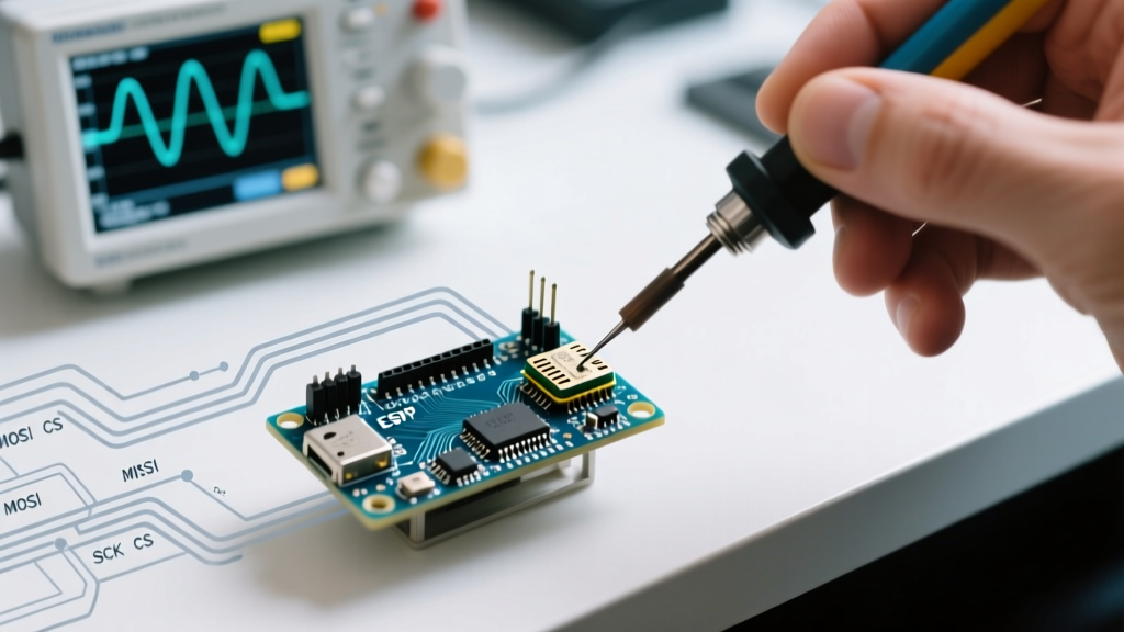
Software optimization is useless if your hardware bus suffers from signal degradation. When pushing the SPI port on Arduino boards beyond 10MHz, parasitic capacitance and trace inductance cause severe edge rounding and ringing.
The Capacitance Limit
A standard FR4 PCB trace exhibits roughly 1.5pF per inch. A 6-inch SPI bus routing adds 9pF. Every slave device's MISO/MOSI input pin adds approximately 10pF. If you daisy-chain three SPI sensors, your total bus capacitance approaches 40pF. At 20MHz, the RC time constant of the GPIO driver and this capacitance will round your square waves into sine waves, causing the slave devices to misread clock edges.
Advanced Routing & Termination Rules
- Series Termination: Solder 33Ω to 47Ω series resistors on the MOSI and SCK lines as close to the master (Arduino) as possible. This matches the output impedance of the microcontroller GPIO to the trace impedance, eliminating high-frequency ringing.
- MISO Isolation: Never put series resistors on the MISO line. The slave device's drive strength is already weak; adding resistance will destroy the rise time.
- Ground Return Path: Ensure a continuous ground plane exists directly beneath the SPI traces. If the ground plane is fractured, the return current will loop around the gap, creating an inductive antenna that radiates EMI and induces crosstalk into adjacent analog sensor lines.
Expert Troubleshooting Matrix
When your logic analyzer shows anomalies, use this diagnostic matrix to isolate the fault.
| Oscilloscope / Logic Analyzer Symptom | Root Cause | Actionable Fix |
|---|---|---|
| MOSI data shifts by 1 bit at high speeds | Setup/Hold time violation due to trace capacitance | Lower SPI clock by 25% or add a 74LVC125A bus buffer. |
| Random 0xFF returns from MISO | Slave not selected, or MISO floating | Verify CS pin logic. Add a 10kΩ pull-up on MISO if bus is shared with non-SPI devices. |
| SCK shows massive overshoot/ringing | Impedance mismatch and lack of termination | Add 33Ω series termination resistor near the master SCK pin. |
| First byte received is correct, rest are 0x00 | CS line toggling too fast before transaction ends | Add a 5µs delay between CS LOW and first SCK edge. |
Mastering the SPI port on Arduino requires moving beyond the abstraction layer. By implementing strict transaction management, leveraging DMA for heavy payloads, respecting CPOL/CPHA timing matrices, and treating your PCB traces as high-speed transmission lines, you can build embedded systems in 2026 that rival commercial industrial hardware in both throughput and reliability.