
The RF24 Library Ecosystem in 2026
When developers search for nrf24l01 arduino solutions, they are almost universally directed to the RF24 library. Originally pioneered by TMRh20 and now maintained by the nRF24 open-source organization, this library remains the gold standard for 2.4GHz ISM band communication on microcontrollers. However, copying and pasting basic example code rarely yields reliable results in real-world environments. Electromagnetic interference, power supply sag, and SPI clock mismatches routinely cause packet loss and silent failures.
This deep dive bypasses the basic "blink an LED over RF" tutorials. Instead, we will dissect the hardware realities of the nRF24L01+ silicon, optimize the RF24 library initialization parameters, and solve the most insidious edge cases involving payload struct alignment and SPI bus contention.
Hardware Reality Check: Base vs. PA+LNA Modules
Before writing a single line of code, you must understand the physical limitations of your transceiver. The market is flooded with two primary variants of the nRF24L01+ module. Choosing the wrong one for your power architecture will guarantee failure.
| Feature | Base nRF24L01+ (PCB Antenna) | nRF24L01+ PA+LNA (External Antenna) |
|---|---|---|
| Typical Cost (2026) | $1.50 - $2.50 | $6.00 - $9.50 |
| TX Current (0dBm) | 11.3 mA | ~35 mA |
| TX Current (+20dBm) | N/A | 115 mA - 120 mA |
| Max Range (Line of Sight) | ~30 meters | ~800 - 1100 meters |
| Power Supply Requirement | Arduino 3.3V Pin (sometimes) | Dedicated External 3.3V LDO |
According to the Nordic Semiconductor nRF24L01+ Product Specification, the chip itself operates between 1.9V and 3.6V. However, the PA+LNA modules integrate amplifiers (like the RFX24C01) that demand transient current spikes exceeding 115mA. The onboard 3.3V regulator of a standard Arduino Uno R3 can only supply roughly 50mA to 150mA total across all 3.3V peripherals. Attempting to drive a PA+LNA module directly from the Arduino's 3.3V pin will result in brownouts, SPI corruption, and module lockups.
Power Supply Decoupling: The #1 Failure Mode
If your radio.available() function randomly returns false, or your transmitter fails to auto-acknowledge, your power rail is likely sagging during TX/RX state transitions. The nRF24L01+ switches states in microseconds, creating high-frequency current demands that long Dupont wires cannot satisfy due to parasitic inductance.
The Mandatory Decoupling Protocol
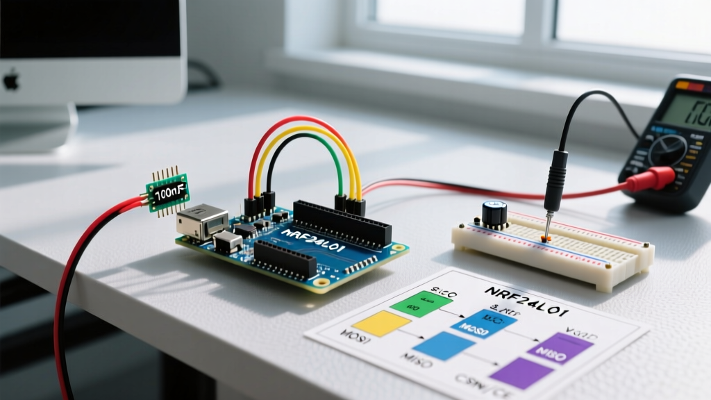
- Bulk Capacitor: Solder a 10µF to 47µF electrolytic or tantalum capacitor directly across the VCC and GND pins on the nRF24L01 module itself. Do not place it on the breadboard; it must be as close to the module pins as physically possible.
- High-Frequency Bypass: Add a 0.1µF (100nF) ceramic capacitor in parallel with the bulk capacitor to filter high-frequency SPI noise.
- External LDO: For PA+LNA modules, use a dedicated AMS1117-3.3 or HT7333 LDO regulator powered from the Arduino's 5V VIN pin, ensuring the LDO can handle at least 250mA continuous current.
SPI Clock Speed and Wiring Nuances
The nRF24L01+ communicates via SPI. By default, the RF24 library initializes the SPI bus at 10MHz on AVR-based Arduinos. While the silicon supports up to 10MHz, real-world wiring capacitance often degrades signal integrity at this speed, leading to corrupted register reads.
Expert Tip: If you are using standard 20cm female-to-female jumper wires, the parasitic capacitance will likely cause SPI failures at 10MHz. Always downgrade the SPI clock speed in your initialization sequence when using non-PCB-mounted modules.
You can override the default SPI speed directly in the begin() function. As noted in the Arduino SPI Reference Documentation, managing bus speed is critical for multi-device SPI networks.
#include <SPI.h>
#include <nRF24L01.h>
#include <RF24.h>

// CE on Pin 7, CSN on Pin 8
RF24 radio(7, 8);

void setup() {
  // Force SPI clock to 4MHz to compensate for long jumper wires
  radio.begin(7, 8, 4000000);
}
Furthermore, the nRF24L01+ logic pins are 5V tolerant on the inputs (MOSI, SCK, CSN, CE), but the MISO output is strictly 3.3V. Most modern AVR and ARM microcontrollers will reliably read 3.3V as a logic HIGH, but if you are integrating with older 5V-only logic families, a bidirectional logic level shifter is mandatory.
Deep Dive: Configuring the RF24 Object for Reliability
Default library settings prioritize ease of use over robustness. For industrial or high-interference environments, you must manually tune the RF24 parameters. The official RF24 GitHub repository provides extensive documentation on these registers, but here is the optimal configuration matrix for 2026 deployments:
- Data Rate:
radio.setDataRate(RF24_250KBPS);- Drops the speed from 2Mbps to 250Kbps. This drastically increases receiver sensitivity (by roughly 8dB) and extends range, at the cost of airtime. - PA Level:
radio.setPALevel(RF24_PA_MIN);- If your nodes are within 5 meters of each other, usingRF24_PA_MAXwill actually cause receiver front-end saturation and packet loss. Always use the minimum power required for the link distance. - Auto-Retries:
radio.setRetries(5, 15);- This configures the auto-acknowledge (Auto-ACK) feature. The first parameter (5) sets the retry delay to 1500µs (5 * 250µs + 250µs base). The second parameter (15) sets the maximum retry count. This gives the receiver ample time to process the payload and send the ACK packet back before the transmitter retries. - Channel Selection:
radio.setChannel(108);- The 2.4GHz band is saturated with WiFi and Bluetooth. WiFi channels 1, 6, and 11 occupy specific spectrums. Channel 108 (2.508 GHz) sits safely above the standard WiFi channel 11 upper bound, minimizing co-channel interference.
Advanced Edge Case: Struct Packing and Payload Alignment
One of the most frustrating bugs in nRF24L01 Arduino programming occurs when transmitting custom C++ structs between different architectures (e.g., an 8-bit Arduino Uno to a 32-bit ESP32). The nRF24L01+ hardware buffer is strictly limited to 32 bytes per payload.
Compilers automatically insert "padding" bytes into structs to align variables with memory boundaries. A 32-bit ARM compiler will pad a struct differently than an 8-bit AVR compiler. If you transmit a 12-byte struct from an Uno, the ESP32 might expect 16 bytes due to padding, causing the radio.read() function to fail or read garbage data.
The Solution: Forced Packing
Always use compiler directives to force byte-alignment on your payload structs. This ensures the struct occupies the exact same memory footprint regardless of the target architecture.
struct __attribute__((packed)) SensorPayload {
  uint8_t nodeId;       // 1 byte
  float temperature;    // 4 bytes
  float humidity;       // 4 bytes
  uint16_t battery_mV;  // 2 bytes
}; // Total: 11 bytes (Fits safely in 32-byte FIFO)

SensorPayload myData;

void loop() {
  myData.temperature = readTemp();
  radio.write(&myData, sizeof(myData));
}
Troubleshooting Matrix: Symptoms and Solutions
When your nrf24l01 arduino link fails, use this diagnostic matrix to isolate the fault domain. Do not blindly rewrite code; verify the physical and SPI layers first.
| Symptom | Probable Cause | Actionable Fix |
|---|---|---|
radio.isChipConnected() returns false |
SPI bus failure, bad wiring, or 3.3V logic mismatch on MISO. | Check MISO connection. Verify SPI clock speed is < 4MHz. Ensure CSN/CE pins match constructor. |
radio.write() returns false (Timeout) |
Receiver is off, wrong address, or severe RF interference. | Verify receiver is in startListening(). Check openReadingPipe and openWritingPipe addresses match exactly. |
| Works on bench, fails when moved 2 meters away | Receiver saturation (PA level too high) or power supply sag. | Lower TX power via setPALevel(RF24_PA_LOW). Add 47µF capacitor to TX module VCC/GND. |
| Random corrupted floats/ints in payload | Struct padding mismatch between TX and RX architectures. | Apply __attribute__((packed)) to payload structs on both nodes. |
| Module gets hot to the touch | Overvoltage (connected to 5V instead of 3.3V). | Immediately disconnect. The module is likely permanently damaged. Replace and verify LDO output. |
Moving Beyond Point-to-Point: RF24Network
While the base RF24 library handles point-to-point and simple star topologies via pipes, managing addresses for a mesh of 20+ sensors becomes a logistical nightmare. For complex deployments, transition to the RF24Network layer. This library sits on top of RF24 and implements a tree-routing topology using octal addressing (e.g., Node 01, Node 021, Node 0321). It handles packet fragmentation, automatic routing, and ACK management, allowing you to build robust, multi-hop sensor networks without manually managing the 6 available hardware data pipes.
Mastering the nRF24L01+ requires treating it not just as a software peripheral, but as a mixed-signal RF component. By respecting its power transient requirements, tuning the SPI bus to match your physical wiring, and enforcing strict data alignment, you can achieve years of reliable, low-latency wireless communication in your embedded projects.