
Beyond the Analog Read: Communicating Potentiometer Data
Most beginner tutorials end at analogRead(A0). But in professional and advanced DIY projects, reading the voltage is only 10% of the battle. The real challenge lies in the potentiometer code Arduino communication pipeline: transmitting that data reliably to a PC, a DAW (Digital Audio Workstation), or a secondary microcontroller without jitter, latency, or dropped packets.
This guide bypasses the basics and dives straight into advanced communication setups for 2026, covering UART packet framing, native USB MIDI bit-shifting, and I2C telemetry. We will also address the hardware edge cases that cause ADC (Analog-to-Digital Converter) noise in the first place.
The Hardware Baseline: Source Impedance and Noise
Before writing communication code, your hardware must be optimized for the ATmega328P or ATmega32U4 ADC. The official Arduino analogRead() documentation and the Microchip datasheet explicitly state that the ADC requires a source impedance of 10 kΩ or less to charge the internal sample-and-hold capacitor within the 1.5 ADC clock cycles allocated.
Component Selection
- Optimal Component: Bourns PTV09A-4025F-B103 (10K Linear, 9mm, knurled shaft). Costs roughly $1.15 via Mouser or DigiKey.
- Avoid: 100K or 1M audio taper (logarithmic) pots for precision data transmission, as their high impedance invites electromagnetic interference (EMI) and causes missing codes in the ADC.
The 100nF Wiper Bypass
Always solder a 100nF (0.1µF) X7R ceramic capacitor directly between the potentiometer's wiper (middle pin) and GND. This forms a low-pass filter that eliminates high-frequency RF noise and mechanical contact bounce before the signal even reaches the microcontroller's ADC pin.
Core Signal Processing: Exponential Moving Average (EMA)
Raw ADC values fluctuate by ±2 to ±4 bits due to thermal noise. Sending raw data over Serial or MIDI will cause "parameter jumping" in your receiving software. Instead of a memory-heavy averaging array, use an Exponential Moving Average (EMA) in your potentiometer code Arduino sketch.
// EMA Filter for Jitter Removal
float alpha = 0.15; // Smoothing factor (0.0 to 1.0)
float smoothVal = 0;

void setup() {
  Serial.begin(115200);
}

void loop() {
  int rawVal = analogRead(A0);
  smoothVal = (alpha * rawVal) + ((1.0 - alpha) * smoothVal);

  // Proceed to communication protocols using (int)smoothVal
}
Protocol 1: High-Speed UART Serial with Packet Framing
When sending potentiometer data to Python (via pyserial) or Processing, using Serial.println(val) is a rookie mistake. It lacks synchronization, leading to torn bytes if the PC reads the serial buffer mid-transmission.
ASCII Packet Framing
Wrap your data in start and end markers. This allows the receiving Python script to use regex or simple string splitting to extract clean integers.
void transmitSerial(int smoothedData) {
  // Format:
  Serial.print("");
  Serial.write(0x0A); // Newline character for Python readline()
}
Baud Rate Selection: For real-time UI control (like adjusting a motor PID or a software synth filter), set your baud rate to 115200 or 250000. Standard 9600 baud introduces a ~1ms latency per byte, which compounds into noticeable UI lag when transmitting multiple sensor arrays.
Protocol 2: Native USB MIDI for Audio Controllers
Building a custom MIDI controller? If you are using an Arduino Leonardo, Micro, or Nano Every (ATmega4809), you can send native USB MIDI Control Change (CC) messages.
The MIDI Association specification dictates that standard CC values are 7-bit (0 to 127). The Arduino ADC is 10-bit (0 to 1023).
The Bit-Shifting Trick (Avoid the map() Bug)
Many developers use map(val, 0, 1023, 0, 127). However, due to integer math rounding, an ADC reading of 1023 will sometimes map to 128, which is an invalid 7-bit MIDI byte and will crash or corrupt the MIDI stream in your DAW.
The Expert Fix: Use bitwise right-shift.
#include

void sendMIDI_CC(byte control, int adc_10bit) {
  // Right shift by 3 divides by 8.
  // Max 1023 >> 3 equals exactly 127. No overflow possible.
  byte cc_val = adc_10bit >> 3;

  midiEventPacket_t event = {0x0B, 0xB0, control, cc_val};
  MidiUSB.sendMIDI(event);
  MidiUSB.flush();
}
Pro-Tip for MIDI: Only transmit the MIDI CC message if the EMA-filtered value changes by at least 2 bits from the last transmitted value. This "deadband" logic prevents a continuous stream of identical MIDI messages that can overload older hardware synths.
Protocol 3: I2C Master-Slave Telemetry
When building a modular synthesizer or a robotic arm, you may need to offload the potentiometer reading to a slave MCU (like an ATTiny85) to save GPIO pins on your main processor. I2C is ideal for this short-distance communication.
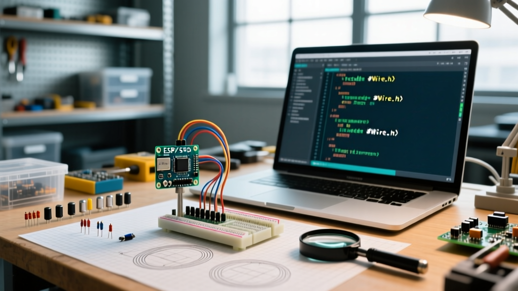
#include
#define SLAVE_ADDR 0x08

void transmitI2C(int smoothedData) {
  Wire.beginTransmission(SLAVE_ADDR);
  // Split 10-bit int into two 8-bit bytes for I2C bus
  Wire.write(highByte(smoothedData));
  Wire.write(lowByte(smoothedData));
  Wire.endTransmission();
}
Ensure you have 4.7kΩ pull-up resistors on both SDA and SCL lines if your wire run exceeds 10 centimeters. For runs up to 1 meter, drop to 2.2kΩ pull-ups to combat line capacitance, a concept detailed in SparkFun's ADC and digital signaling guides.
Communication Protocol Comparison Matrix
| Protocol | Max Speed / Latency | Wiring Complexity | Best Use Case (2026) |
|---|---|---|---|
| UART Serial | ~1ms at 115200 baud | Low (TX, RX, GND) | PC GUI dashboards, Python data logging, Processing visualizations. |
| USB MIDI | Sub-1ms (Native USB) | Ultra-Low (USB Cable) | Ableton/FL Studio macro control, lighting desks, DJ controllers. |
| I2C | ~250µs (at 400kHz) | Medium (SDA, SCL, Pull-ups) | Inter-MCU communication, modular synth CV routing, robotic joints. |
Troubleshooting Edge Cases
1. The "Ground Loop" Jitter
If your potentiometer values jump wildly when a motor or LED strip turns on, you are experiencing a ground loop. The high current draw causes a voltage spike on the shared GND trace, shifting the ADC's 0V reference. Solution: Use a star-ground topology, routing the potentiometer's GND directly to the Arduino's main GND pin, separate from high-current load grounds.
2. VCC Noise from Switching Regulators
Powering your project via a cheap buck converter introduces high-frequency switching noise directly into the ATmega's VCC, which the ADC uses as its default reference. Solution: Add an external 3.3V LDO (like the AMS1117-3.3) and use analogReference(EXTERNAL) in your setup function. This locks the ADC ceiling to a clean, ripple-free voltage.
Frequently Asked Questions
Can I use a 100K potentiometer to save battery power?
Not directly. A 100K pot exceeds the 10K source impedance limit of the Arduino ADC, resulting in inaccurate, lower-than-expected readings. If you must use a high-impedance pot for power saving, buffer the wiper signal with an op-amp (like the MCP6001) configured as a voltage follower before feeding it to the Arduino.
How do I map the potentiometer to a specific non-linear curve?
For audio volume controls, human hearing is logarithmic. Instead of a linear map, apply a power function in your code: float audioVal = pow(smoothVal / 1023.0, 3.0) * 1023;. This creates an exponential curve that feels natural to the human ear when transmitted to a digital amplifier.