
Why the Blink Sketch is the Ultimate Microcontroller Baseline
Every embedded systems engineer, from hobbyists to aerospace firmware developers, starts with the same fundamental test: making an LED blink. Writing your first Arduino flashing LED code is not just a rite of passage; it is a critical diagnostic tool. It verifies your toolchain, confirms your microcontroller's clock speed, tests your GPIO (General Purpose Input/Output) pin drivers, and validates your physical wiring.
While the concept is simple, executing it correctly requires understanding the intersection of hardware physics and software architecture. In this guide, we will move beyond the basic delay() function that traps most beginners, and explore professional, non-blocking timing techniques using modern boards like the Arduino Uno R4 Minima ($20.00) and the Nano ESP32 ($21.00).
Hardware Selection and Precision Wiring
Before writing a single line of code, you must build a safe physical circuit. Connecting an LED directly to a GPIO pin without a current-limiting resistor will draw excessive current, potentially damaging the microcontroller's internal silicon traces or the LED itself.
Calculating the Correct Resistor Value
We will use a standard Kingbright WP710A102LSURCK 5mm Red LED. According to its datasheet, it has a Forward Voltage ($V_f$) of 2.0V and a maximum continuous Forward Current ($I_f$) of 20mA. To calculate the required resistor, we use Ohm's Law: $R = (V_s - V_f) / I_f$, where $V_s$ is the supply voltage of your specific Arduino board.
| Board Model | Logic Level ($V_s$) | Target Current | Calculated Resistance | Recommended E12 Value | Estimated Cost |
|---|---|---|---|---|---|
| Arduino Uno R4 Minima | 5.0V | 20mA | 150Ω | 150Ω or 220Ω | $20.00 |
| Arduino Uno R3 (Classic) | 5.0V | 20mA | 150Ω | 150Ω or 220Ω | $27.00 |
| Arduino Nano ESP32 | 3.3V | 20mA | 65Ω | 68Ω or 100Ω | $21.00 |
Expert Tip: Never rely on Pin 13 for external breadboard LEDs on older Uno R3 boards. Pin 13 is tied to the onboard diagnostic LED and often features an op-amp buffer or pull-down resistor that can cause external LEDs to glow dimly or behave erratically. Always use a dedicated digital pin like Pin 8 for external circuits.
Step-by-Step Breadboard Wiring
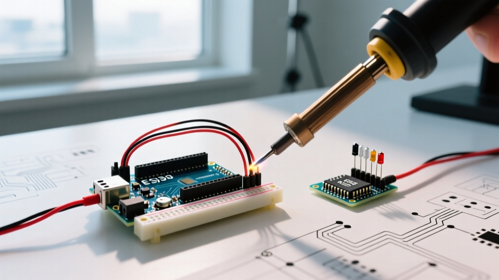
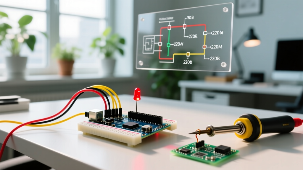
- Insert the Arduino Uno R4 Minima into your workspace and ensure it is powered off.
- Place the 220Ω resistor across the center trench of your breadboard.
- Connect one leg of the resistor to Digital Pin 8 using a jumper wire.
- Insert the anode (the longer leg) of the red LED into the same row as the other end of the resistor.
- Insert the cathode (the shorter leg, flat side of the bulb) into an empty row.
- Connect the cathode row to the Arduino's GND pin using a black jumper wire.
Level 1: The Basic Arduino Flashing LED Code (Blocking)
The standard approach taught in introductory tutorials uses the delay() function. This method is perfectly fine for single-task diagnostics but is considered "blocking" code.
// Basic Blocking Blink Sketch
const int LED_PIN = 8;

void setup() {
  // Initialize the digital pin as an output
  pinMode(LED_PIN, OUTPUT);
}

void loop() {
  digitalWrite(LED_PIN, HIGH); // Turn the LED on (5V or 3.3V)
  delay(1000);                 // Pause execution for 1000ms (1 second)
  digitalWrite(LED_PIN, LOW);  // Turn the LED off (0V)
  delay(1000);                 // Pause execution for 1000ms
}
The Problem with delay()
When the microcontroller executes delay(1000), it does exactly that: it halts all other operations. It cannot read sensors, listen for Bluetooth UART commands, or update a display. The CPU is essentially frozen in a counting loop. If you want to build a project that blinks an LED while reading a temperature sensor, the blocking method will fail.
Level 2: Professional Non-Blocking Arduino Flashing LED Code
To write robust firmware, you must learn to track time without stopping the processor. We achieve this using the millis() function, which returns the number of milliseconds since the board began running the current program. For a deep dive into the official architecture, refer to the Arduino BlinkWithoutDelay Documentation.
// Non-Blocking Millis() Blink Sketch
const int LED_PIN = 8;
const long BLINK_INTERVAL = 1000; // Interval in milliseconds

int ledState = LOW;               // Current state of the LED
unsigned long previousMillis = 0; // Stores the last time the LED was updated

void setup() {
  pinMode(LED_PIN, OUTPUT);
}

void loop() {
  // Check to see if it's time to blink the LED
  unsigned long currentMillis = millis();

  if (currentMillis - previousMillis >= BLINK_INTERVAL) {
    // Save the last time you blinked the LED
    previousMillis = currentMillis;

    // Toggle the LED state
    if (ledState == LOW) {
      ledState = HIGH;
    } else {
      ledState = LOW;
    }

    // Apply the new state to the hardware pin
    digitalWrite(LED_PIN, ledState);
  }

  // You can add other non-blocking code here!
  // readSensors();
  // checkWiFi();
}
The 49.7-Day Unsigned Long Overflow Edge Case
Beginners often ask: "What happens when millis() reaches the maximum value of an unsigned long (4,294,967,295 milliseconds, or about 49.7 days) and rolls over to zero? Won't the math break?"
The answer is no, provided you use the subtraction method shown above: currentMillis - previousMillis >= interval. Because we are using unsigned integer arithmetic, the overflow wraps around perfectly. If previousMillis was 4,294,967,290 and currentMillis rolled over to 10, the subtraction yields exactly 15. Attempting to use addition (e.g., if (currentMillis >= previousMillis + interval)) will cause a catastrophic logic failure at the 49.7-day mark. Always use subtraction for time deltas.
Hardware Troubleshooting and Failure Modes
Even with perfect code, physical layer issues frequently stump beginners. Here is a diagnostic matrix for common failures.
- LED is extremely dim: You likely used a resistor with too high a value (e.g., 10kΩ instead of 220Ω), or you are accidentally using a PWM pin with a low default duty cycle. Verify your resistor color bands (Red-Red-Brown-Gold for 220Ω).
- Code uploads successfully, but LED stays off: Check LED polarity. The anode (long leg) must face the GPIO pin, and the cathode (short leg) must face GND. Unlike incandescent bulbs, LEDs are diodes and only allow current to flow in one direction.
- Upload fails with "Port not found" on a clone board: If you purchased a budget-friendly Uno R3 clone (often priced around $12.00), it likely uses the CH340G USB-to-Serial chip instead of the official Atmega16U2. You must manually download and install the CH340G drivers from the manufacturer for your OS (Windows/macOS) before the IDE will recognize the COM port.
- LED flickers rapidly instead of a clean 1-second blink: This usually indicates a floating ground or a loose breadboard connection. Ensure your GND jumper wire is firmly seated in the power rail. For high-vibration environments, consider soldering the components to a perfboard rather than relying on breadboard friction clips.
Next Steps: Expanding Your Firmware
Once you have mastered the non-blocking Arduino flashing LED code, you have unlocked the foundational architecture for all real-time embedded systems. From here, you can integrate I2C OLED displays, read analog thermistors, or implement UART serial communication—all running concurrently in the loop() without interrupting your precise LED timing.
For further reading on component physics and current limiting, the SparkFun LED Tutorial provides excellent visual breakdowns of forward voltage curves and diode behavior.
Pro Tip for 2026: If you are using the newer Arduino Uno R4 WiFi, take advantage of its 12-bit DAC and advanced LED matrix. However, for standard external GPIO blinking, the 5V logic and millis() principles outlined above remain universally applicable across the entire AVR and ARM Cortex-M4 ecosystem.