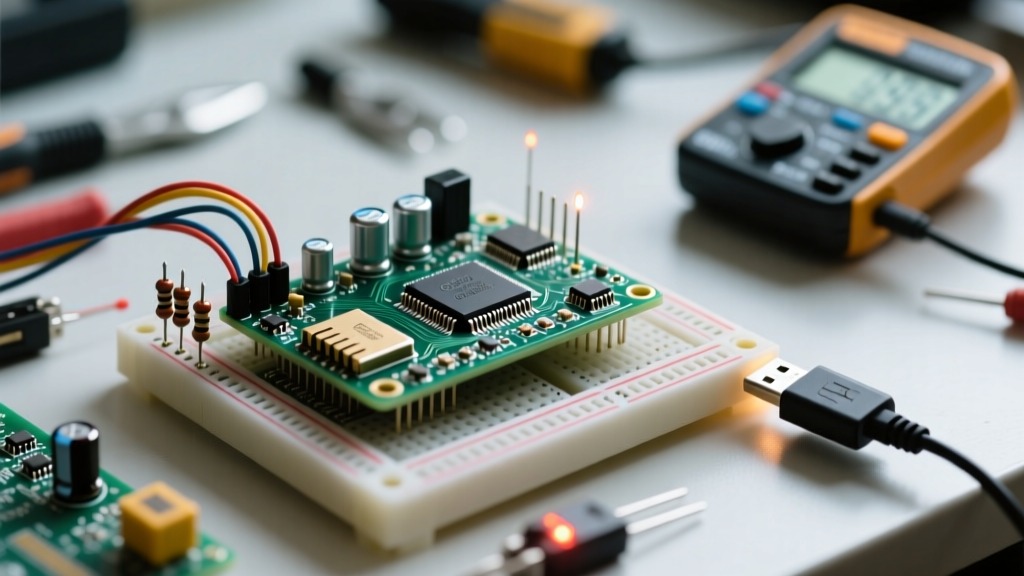
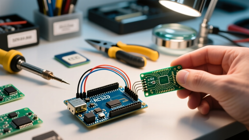
The Reality of Physical Traffic Light Prototypes
Writing a basic traffic light code for Arduino is a universal rite of passage for embedded systems beginners. In a simulated environment like Tinkercad, a few digitalWrite() and delay() commands yield a perfect, predictable sequence. However, migrating that exact same code to a physical breadboard with an Arduino Uno R3 ($27) or the newer Uno R4 Minima ($20) often exposes hidden hardware and software faults. LEDs flicker, timing drifts, and adding a simple pedestrian crosswalk button breaks the entire sequence.
This guide moves beyond basic tutorials. We will debug the most common failure modes in traffic light implementations, focusing on non-blocking timing architectures, precise forward-voltage hardware calculations, and interrupt-driven edge cases.
The 'Blocking Code' Trap and Timing Drift
The most frequent architectural flaw in beginner traffic light code for Arduino is the reliance on the delay() function. When you call delay(4000) for a red light, the microcontroller is completely paralyzed. It cannot poll sensors, read pedestrian buttons, or update serial telemetry. Furthermore, cumulative timing drift occurs due to instruction execution overhead.
Symptom: Unresponsive Pedestrian Buttons
If your traffic light cycle takes 9 seconds (4s Red + 1s Yellow + 4s Green) using delays, a pedestrian pressing a button on second 2 will experience a 7-second latency. In real-world traffic management systems, this is unacceptable.
The Fix: Non-Blocking State Machines
To resolve this, you must implement a finite state machine (FSM) using the millis() function. As detailed in the official Arduino BlinkWithoutDelay documentation, tracking elapsed time allows the MCU to perform background tasks while waiting for the light to change.
enum LightState { RED, YELLOW, GREEN };
LightState currentState = RED;
unsigned long previousMillis = 0;
const long redInterval = 4000;
const long yellowInterval = 1000;
const long greenInterval = 4000;

void updateTrafficLight() {
  unsigned long currentMillis = millis();
  unsigned long interval = 0;

  switch (currentState) {
    case RED: interval = redInterval; break;
    case YELLOW: interval = yellowInterval; break;
    case GREEN: interval = greenInterval; break;
  }

  if (currentMillis - previousMillis >= interval) {
    previousMillis = currentMillis;
    advanceState();
  }
}
Hardware Debugging Matrix: LED Faults & Voltage Drops
Software is only half the battle. Hardware mismatches cause visual anomalies that developers often try to fix with software PWM, wasting clock cycles. Standard 5mm through-hole LEDs have different forward voltages (Vf) and luminous intensities. According to SparkFun's Diode and LED Tutorial, applying the same current-limiting resistor to all colors results in mismatched brightness.
| Observed Symptom | Root Cause (Hardware/Code) | Diagnostic Step | Engineered Solution |
|---|---|---|---|
| Green LED is noticeably dimmer than Red | Higher Vf of Green LED (approx 3.2V vs 2.0V for Red) causes lower current draw with identical resistors. | Measure voltage across the LED with a multimeter. Calculate actual current using Ohm's Law. | Use a 100Ω resistor for Green (yielding ~18mA) and a 150Ω resistor for Red (yielding ~20mA). |
| Faint 'ghost' glow when LED is supposed to be OFF | Floating pins or capacitive coupling on long breadboard jumper wires. | Disconnect the GPIO wire. If the glow persists, it's leakage from the breadboard power rails. | Ensure pinMode is explicitly set to OUTPUT. Add a 10kΩ pull-down resistor from the anode to GND. |
| LEDs flicker randomly during Serial.print() | Power supply brownout. USB ports often limit current to 500mA; multiple high-brightness LEDs cause voltage sag. | Monitor the 5V rail with an oscilloscope or multimeter during Serial transmission bursts. | Power the breadboard via an external 5V 2A buck converter rather than the Arduino's onboard 5V pin. |
| Yellow light duration is inconsistent | Using delayMicroseconds() on an Arduino Uno R4 Minima (48MHz) vs R3 (16MHz) without adjusting for clock speed. |
Verify the exact board architecture in the IDE. Check compiler warnings regarding timing functions. | Stick to millis() for macro-timing (milliseconds). Avoid hardware-dependent microsecond loops. |
Handling Edge Cases: Pedestrian Interrupts & Switch Bounce
Once your non-blocking traffic light code for Arduino is stable, you will likely add a pedestrian crosswalk button. Connecting a mechanical momentary switch directly to a digital input and using an interrupt is the standard approach, but it introduces switch bounce.
Expert Warning: A standard tactile switch will mechanically bounce for 1 to 5 milliseconds upon actuation. If your interrupt service routine (ISR) triggers onFALLINGorRISING, a single button press can register as 10-20 separate interrupts, instantly corrupting your state machine variables.
Hardware vs. Software Debouncing
You have two professional avenues to resolve this:
- Hardware Debouncing: Place a 100nF (0.1µF) ceramic capacitor in parallel with the switch terminals. This creates a low-pass RC filter that absorbs the high-frequency bounce spikes. This is the preferred method for safety-critical systems as it prevents the MCU from ever seeing the noisy signal.
- Software Debouncing: If hardware modifications aren't possible, do not write your own delay-based debounce logic inside the ISR. Instead, use the attachInterrupt() function to set a simple volatile boolean flag, and handle the 50ms debounce timer inside your main
loop()using themillis()FSM logic.
Power Architecture: Uno R3 vs. Uno R4 Minima
As of 2026, the transition from the classic ATmega328P-based Uno R3 to the Renesas RA4M1-based Uno R4 Minima has introduced new debugging variables. The R4 Minima operates at 48MHz and features a 12-bit DAC and advanced PWM capabilities. However, its GPIO absolute maximum current rating per pin is slightly different, and the internal voltage regulator topology has changed.
If you are multiplexing a 4-way intersection (12 LEDs total) directly from the GPIO pins, you risk exceeding the aggregate current limit of the microcontroller's VCC/GND pins (typically 200mA for the ATmega328P). Never drive more than 3 standard 20mA LEDs directly from a single Arduino's GPIO bank without logic-level MOSFETs (like the IRLZ44N) or a ULN2803 Darlington transistor array.
Systematic Troubleshooting Checklist
Before rewriting your traffic light code for Arduino, run through this hardware and software diagnostic checklist:
- Verify Pin Mapping: Ensure the physical breadboard layout matches the
#definemacros at the top of your sketch. Off-by-one errors in pin arrays are common. - Check Resistor Tolerances: Standard carbon film resistors have a 5% tolerance. If your LEDs are slightly mismatched, measure the actual resistance with a DMM.
- Isolate the Code: Comment out all Serial debugging prints.
Serial.println()takes roughly 1-2ms per execution at 9600 baud. In a tight loop, this will visibly alter your traffic light timing. - Inspect Ground Loops: If using an external power supply for the LEDs, ensure the external GND is physically tied to the Arduino GND. Without a common ground reference, the GPIO signals will float, causing erratic LED behavior.
Conclusion
Mastering the traffic light code for Arduino is less about memorizing syntax and more about understanding the intersection of real-time operating constraints and physical electronics. By abandoning blocking delays in favor of millis() driven state machines, calculating precise current-limiting resistors based on LED forward voltages, and properly debouncing mechanical inputs, you transform a fragile beginner project into a robust, production-ready embedded system.