
The Anatomy of an Arduino SPI Failure
Serial Peripheral Interface (SPI) is the backbone of high-speed sensor and memory communication in embedded systems. Unlike I2C, which relies on pull-up resistors and open-drain lines, SPI uses push-pull outputs, allowing for clock speeds exceeding 50 MHz. However, this raw speed makes the Arduino SPI bus highly susceptible to signal integrity issues, timing violations, and configuration mismatches.
Whether you are interfacing a W25Q128 flash memory chip with a Nano ESP32 or reading an ADXL345 accelerometer on an Uno R4 Minima, a failed SPI handshake usually boils down to one of seven specific hardware or software faults. This guide bypasses generic advice and dives into the exact edge cases, propagation delays, and register configurations that cause SPI bus failures in 2026.
Error 1: MISO and MOSI Cross-Wired (The Classic Swap)
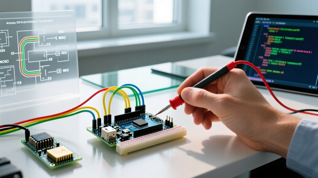
The most frequent cause of a dead SPI bus is swapping Master-In-Slave-Out (MISO) and Master-Out-Slave-In (MOSI). The naming convention refers to the Master's perspective, which confuses many developers when reading slave module silkscreens.
- MOSI: Data flows from the Arduino (Master) to the peripheral (Slave).
- MISO: Data flows from the peripheral (Slave) to the Arduino (Master).
Pro Tip: If your slave module labels its pins as 'DI' (Data In) and 'DO' (Data Out), wire Arduino MOSI to DI, and Arduino MISO to DO. Always trace the signal from the Master's point of view.
On the classic ATmega328P (Uno/Nano), the hardware SPI pins are strictly fixed: MOSI is Pin 11, MISO is Pin 12, and SCK is Pin 13. On newer boards like the Arduino Uno R4 Minima or Nano ESP32, SPI pins can be mapped to alternate GPIOs via the internal pinmux, but relying on the default hardware SPI bus is always recommended for DMA (Direct Memory Access) stability.
Error 2: Clock Speed (SCK) Exceeding Slave Capabilities
Pushing the SPI clock too high results in corrupted payloads or complete bus lockups. While the ATmega328P can theoretically divide its 16 MHz system clock down to 8 MHz for SPI, many peripheral modules cannot keep up due to internal logic delays or long, unshielded ribbon cables acting as antennas.
Common SPI Slave Maximum Clock Speeds
| Component / Module | Typical Max SCK (SPI Mode) | Common Failure Symptom if Exceeded |
|---|---|---|
| MFRC522 (RFID) | 10 MHz | UID reads return all zeros or 0xFF |
| MicroSD (SPI Mode) | 25 MHz | File system corruption, CRC errors |
| ADXL345 (Accelerometer) | 5 MHz | Register read/write hangs indefinitely |
| W25Q128 (Flash Memory) | 104 MHz | Requires specific 'Fast Read' opcodes above 50 MHz |
The Fix: Never use SPI.setClockDivider() in modern sketches. Instead, use SPI.beginTransaction() with SPISettings to define the exact maximum speed your target peripheral can handle.
// Safe initialization for an ADXL345 (Max 5MHz, Mode 3)
SPI.beginTransaction(SPISettings(5000000, MSBFIRST, SPI_MODE3));
Error 3: Chip Select (SS) Pin Floating or Misconfigured
A floating Chip Select (CS/SS) line is a silent killer of SPI transactions. If the CS pin is not pulled HIGH when idle, the slave device will attempt to drive the MISO line, colliding with other devices on the bus and causing massive current spikes that can brownout your microcontroller.
Furthermore, on AVR-based Arduinos (like the Uno), the hardware SS pin (Pin 10) must be configured as an OUTPUT in your setup() function, even if you are using Pin 9 or Pin 8 as your actual software CS pin. If Pin 10 is left as an INPUT and accidentally pulled LOW by electrical noise, the ATmega's SPI hardware controller will instantly abort Master mode and revert to Slave mode, freezing your sketch.
Error 4: Logic Level Voltage Mismatches (3.3V vs 5V)
Mixing 5V logic (Arduino Uno/Mega) with 3.3V logic (BME280, ESP8266, modern Flash chips) without level translation will lead to two outcomes: garbled data or destroyed silicon. Feeding 5V into the MISO or SCK pins of a 3.3V device violates absolute maximum ratings.
Many hobbyists attempt to use a simple voltage divider or a CD4050B non-inverting buffer. While a CD4050B works for I2C or low-speed SPI (under 1 MHz), its propagation delay of roughly 50ns to 70ns will cause setup and hold time violations at 8 MHz or higher. According to SparkFun's SPI design guidelines, high-speed SPI requires dedicated MOSFET-based translators.
- Recommended Level Shifters: Texas Instruments TXS0108E or NXP PCA9306.
- Alternative: Use a 3.3V Arduino board (Nano 33 IoT, Portenta H7) to bypass the need for translation entirely.
Error 5: SPI Mode (CPOL/CPHA) Mismatch
SPI does not have a single universal standard for clock polarity (CPOL) and clock phase (CPHA). If your Arduino samples the MISO line on the wrong clock edge, you will read shifted or entirely inverted data. As detailed in Analog Devices' comprehensive SPI interface guide, there are four distinct SPI modes.
SPI Modes Matrix
| SPI Mode | Clock Polarity (CPOL) | Clock Phase (CPHA) | Idle Clock State | Common Devices |
|---|---|---|---|---|
| Mode 0 | 0 | 0 | LOW | MicroSD Cards, W25Q Flash |
| Mode 1 | 0 | 1 | LOW | MAX31855 Thermocouple |
| Mode 2 | 1 | 0 | HIGH | Rare (Some DACs) |
| Mode 3 | 1 | 1 | HIGH | ADXL345, MFRC522 |
The Fix: Always check the 'Digital Interface' timing diagram in the peripheral's datasheet. If the clock idles HIGH, you need Mode 2 or Mode 3. If it idles LOW, you need Mode 0 or Mode 1.
Error 6: Missing Pull-Up Resistors on MISO for Multi-Slave Buses
When daisy-chaining multiple SPI slaves on a single bus, the MISO line is shared. When a slave's CS pin is HIGH, its MISO output enters a high-impedance (tri-state) mode. If the physical traces on your PCB or breadboard are long, parasitic capacitance can cause the MISO line to float erratically between transactions, leading the Master to read phantom data.
Adding a 10kΩ pull-up resistor on the MISO line near the Master ensures the line defaults to a known HIGH state when no slave is actively driving it. Note: Do not add pull-ups to MOSI or SCK, as they are actively driven by the Master's push-pull outputs.
Error 7: DMA Conflicts with Interrupt Service Routines (ISRs)
On advanced boards like the Arduino Portenta H7 or Nano ESP32, SPI transfers are often handled via DMA to free up the CPU. However, if an ISR (Interrupt Service Routine) triggers during a DMA-backed SPI transfer and attempts to use the same SPI bus or modify shared memory buffers without proper mutex locks, the bus will corrupt or crash.
The Fix: Ensure your SPI buffers are declared volatile or protected by RTOS mutexes if using FreeRTOS. Never call SPI.transfer() inside an ISR when DMA is active; instead, set a flag in the ISR and handle the SPI transaction in the main loop().
Advanced Debugging: Using a Logic Analyzer
When code reviews and multimeter continuity tests fail, you must visualize the bus. A $15 24MHz 8-channel logic analyzer clone running on the open-source PulseView / Sigrok platform is mandatory for deep SPI debugging.
- Sampling Rate Rule: Always sample at least 4x to 8x your SPI clock speed. If your SCK is 4 MHz, set the logic analyzer to 24 MHz or higher to accurately capture edge transitions.
- Trigger Setup: Set the trigger to the falling edge of the Chip Select (CS) pin. This ensures you capture the exact moment the transaction begins.
- Protocol Decoding: Assign the MISO, MOSI, SCK, and CS channels in PulseView, select the SPI decoder, and input your expected CPOL/CPHA. The software will translate the raw hex dumps into readable register addresses and payloads, instantly revealing if the slave is NACKing or returning 0xFF due to a wiring fault.
By systematically eliminating these seven physical and logical bottlenecks, you can transform a stubborn, non-responsive SPI bus into a rock-solid, high-throughput data pipeline.