
The "delay()" Trap: Why Your Pedestrian Button is Ignored
Building a basic intersection model is a rite of passage for embedded systems enthusiasts. However, when writing Arduino traffic light code, beginners almost universally fall into the same architectural trap: relying on the delay() function. Your red, yellow, and green LEDs sequence perfectly. But the moment you wire up a pedestrian crossing button to digital pin 2, the system fails. You press the button, and nothing happens. Why?
The delay() function is a blocking command. When your Arduino Uno R4 Minima (currently retailing around $19.99 in 2026) executes delay(5000) to hold the red light, the microcontroller's CPU is effectively paralyzed. It cannot read digital inputs, process sensor data, or update secondary displays. It sits idle, counting clock cycles. If a pedestrian presses the crossing button during that 5-second window, the MCU is entirely deaf to the input. To build responsive, real-world Arduino traffic light code, you must abandon blocking delays and adopt a non-blocking, event-driven architecture.
Refactoring to millis(): The Non-Blocking State Machine
To debug and fix this, we replace time-halting delays with timestamp tracking using the millis() function. This approach, famously demonstrated in the official Arduino BlinkWithoutDelay example, allows the MCU to continuously loop and check for button presses while independently tracking how long an LED has been illuminated.
Designing the State Machine Variables
A robust traffic light controller requires a finite state machine (FSM). Instead of hardcoding a linear sequence, you define states and transitions. You will need the following global variables:
currentLightState: An integer or enum tracking if the light is RED, YELLOW, or GREEN.previousMillis: Stores the exact timestamp when the current light state was initiated.interval: The duration the current state should remain active before transitioning.buttonState&lastButtonState: Variables to track the pedestrian input and manage edge detection.
Expert Insight: Never put
Serial.println()debugging statements inside your primaryloop()without a throttle. Flooding the serial buffer at 115200 baud will introduce micro-delays that distort yourmillis()timing and cause erratic LED flickering.
Hardware Debugging: Electrical & Wiring Faults
Often, the issue isn't the Arduino traffic light code itself, but the physical circuit. If your pedestrian button triggers randomly without being pressed, or your LEDs glow dimly when they should be off, you are dealing with electrical faults.
The Floating Pin Phenomenon
If you wire a pushbutton between a digital pin and ground without a pull-up resistor, the pin becomes "floating" when the button is open. A floating pin acts as an antenna, picking up electromagnetic interference (EMI) from nearby wires, AC mains, or even your body's capacitance. The Arduino interprets this noise as rapid button presses. The software fix is simple: initialize the pin using pinMode(buttonPin, INPUT_PULLUP), which engages the internal 20kΩ–50kΩ resistor, holding the pin HIGH until the button grounds it. For a deeper understanding of this circuit behavior, review the SparkFun guide on pull-up resistors.
Current Limiting and Ohm's Law
Driving LEDs directly from a GPIO pin without current-limiting resistors will degrade the microcontroller's silicon over time. The Arduino Uno R4 can source up to 25mA per pin, but standard 5mm through-hole LEDs are typically rated for 20mA continuous forward current. Use the formula R = (Vs - Vf) / If to calculate the exact resistor needed.
| LED Color | Typical Forward Voltage (Vf) | Target Current (If) | Calculated Resistor (5V Logic) | Recommended Standard Value |
|---|---|---|---|---|
| Red | 2.0V | 20mA | 150Ω | 220Ω |
| Yellow | 2.1V | 20mA | 145Ω | 220Ω |
| Green | 3.2V | 20mA | 90Ω | 100Ω or 150Ω |
Troubleshooting Matrix: Symptoms vs. Root Causes
When your intersection model behaves erratically, use this diagnostic matrix to isolate the fault. This framework separates software logic errors from hardware degradation.
| Observed Symptom | Probable Root Cause | Actionable Fix |
|---|---|---|
| Pedestrian button triggers randomly | Floating input pin / EMI noise | Change INPUT to INPUT_PULLUP in setup(). |
| Green LED is noticeably dimmer than Red | Incorrect resistor value or high Vf | Verify resistor with a multimeter; green LEDs require lower resistance. |
| Button press registers 3-4 times instantly | Mechanical switch contact bounce | Implement software debouncing or add a 0.1µF ceramic capacitor in parallel. |
| Entire sequence freezes after 49 days | Integer overflow on millis() |
Use subtraction for time checks: if (currentMillis - previousMillis >= interval). |
| LEDs "ghost" or glow faintly when OFF | Leakage current or missing ground reference | Ensure all grounds are tied together; check for breadboard stray capacitance. |
Handling Button Bounce and Sensor Noise
Mechanical pushbuttons suffer from contact bounce. When the metal contacts close, they physically vibrate for a few milliseconds, causing the Arduino to read a rapid sequence of HIGH-LOW-HIGH transitions. If your Arduino traffic light code immediately interrupts the red light phase on the first detected LOW, a single pedestrian press might trigger the crossing sequence multiple times or corrupt your state machine variables.
To debug this, you must implement debouncing. The official Arduino Debounce tutorial provides a solid foundation using millis() to ignore state changes that occur within a 50ms window. For complex intersections utilizing inductive loop sensors or ultrasonic vehicle detectors, hardware debouncing via a Schmitt trigger IC (like the 74HC14) is highly recommended to clean up noisy analog signals before they reach the microcontroller's digital pins.
Multimeter Debugging Steps for Hardware Verification
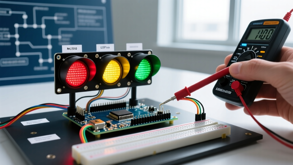
If your code is verified but the hardware remains unresponsive, grab a digital multimeter (such as a Fluke 117) and follow these physical verification steps:
- Verify Logic High: Set the multimeter to DC Voltage. Probe the digital output pin driving the red LED and the Arduino GND. You should read exactly 4.8V to 5.0V. If it reads lower, your USB power supply may be browning out under load.
- Measure Voltage Drop: Probe the legs of your current-limiting resistor. If the voltage drop across a 220Ω resistor is 0V while the LED is supposed to be ON, your GPIO pin is not outputting a signal, indicating a pin-mapping error in your code.
- Check Continuity: Power down the board. Set the multimeter to continuity mode. Probe the pedestrian button leads. Press the button. If the multimeter doesn't beep, the switch is faulty or inserted incorrectly across the breadboard's internal bus divide.
Summary: Writing Production-Ready Intersection Code
Transitioning from a beginner's blocking script to a responsive, non-blocking state machine is the hallmark of competent embedded programming. By utilizing millis() for timing, engaging internal pull-up resistors to stabilize inputs, and applying rigorous hardware debugging with a multimeter, your Arduino traffic light code will be robust enough to handle real-world edge cases, sensor integrations, and continuous 24/7 operation without failing.